M62281P Просмотр технического описания (PDF) - Renesas Electronics
Номер в каталоге
Компоненты Описание
производитель
M62281P Datasheet PDF : 13 Pages
| |||
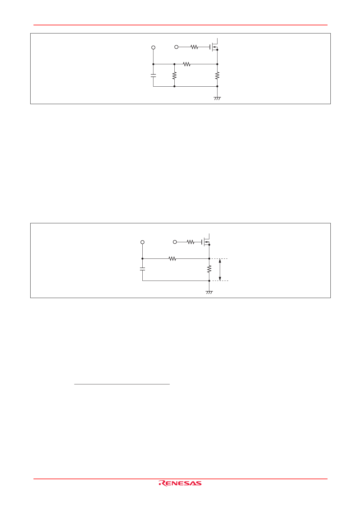
M62281P/FP
CLM OUT
RNF1
CNF
RNF2
RCS
Figure 7-2 Peripheral Circuit of CLM When The Detected Voltage is High
1000 pF to 22000 pF is recommended for CNF. Be sure to use 100 Ω or less for RNF and RNF1 // RNF2 (*) so that the
detection sensitivity is not influenced by the current flown out from CLM terminal.
Non-inductive resistor is recommended for current detecting resistor.
* RNF1 // RNF2 = (RNF1 • RNF2) / (RNF1 + RNF2)
CURRENT SENSE Terminal
The voltage proportional to the switching current is supplied to this terminal.
Output duty is controlled by comparing this voltage with the output of error amp..
CLM and CURRENT SENSE terminal is separate from each other, so various settings are available depending upon the
application.
CURRENT
SENSE
OUT
RNF
CNF
RCS
VCS
Figure 8 Peripheral Circuit of CURRENT SENSE
RCS is determined by :
VCS = (VEA OUT − 1.3) / 3 (V), where VEA OUT represents the voltage of EA OUT terminal.
CF Terminal
Oscillation frequency is set by capacitor connected to CF terminal.
The waveform of CF terminal is triangular one with the ratio of 9 : 1 for charge-discharge period.
Oscillation frequency is represented as :
fOSC =
1
(19.4 × 10³ × COSC) + (0.4 × 10⁻⁶)
(Hz)
REJ03D0840-0201 Rev.2.01 Nov 14, 2007
Page 9 of 12
Share Link: 