UDA1341TS Просмотр технического описания (PDF) - NXP Semiconductors.
Номер в каталоге
Компоненты Описание
производитель
UDA1341TS
NXP Semiconductors.

UDA1341TS Datasheet PDF : 34 Pages
| |||
NXP Semiconductors
Economy audio CODEC for MiniDisc (MD)
home stereo and portable applications
Product specification
UDA1341TS
7.9 Decimation filter (ADC)
The decimation from 128fs is performed in two stages.
The first stage realizes 3rd order
s----i-n-----x-
x
characteristic,
decimating by 16. The second stage consists of
3 half-band filters, each decimating by a factor of 2.
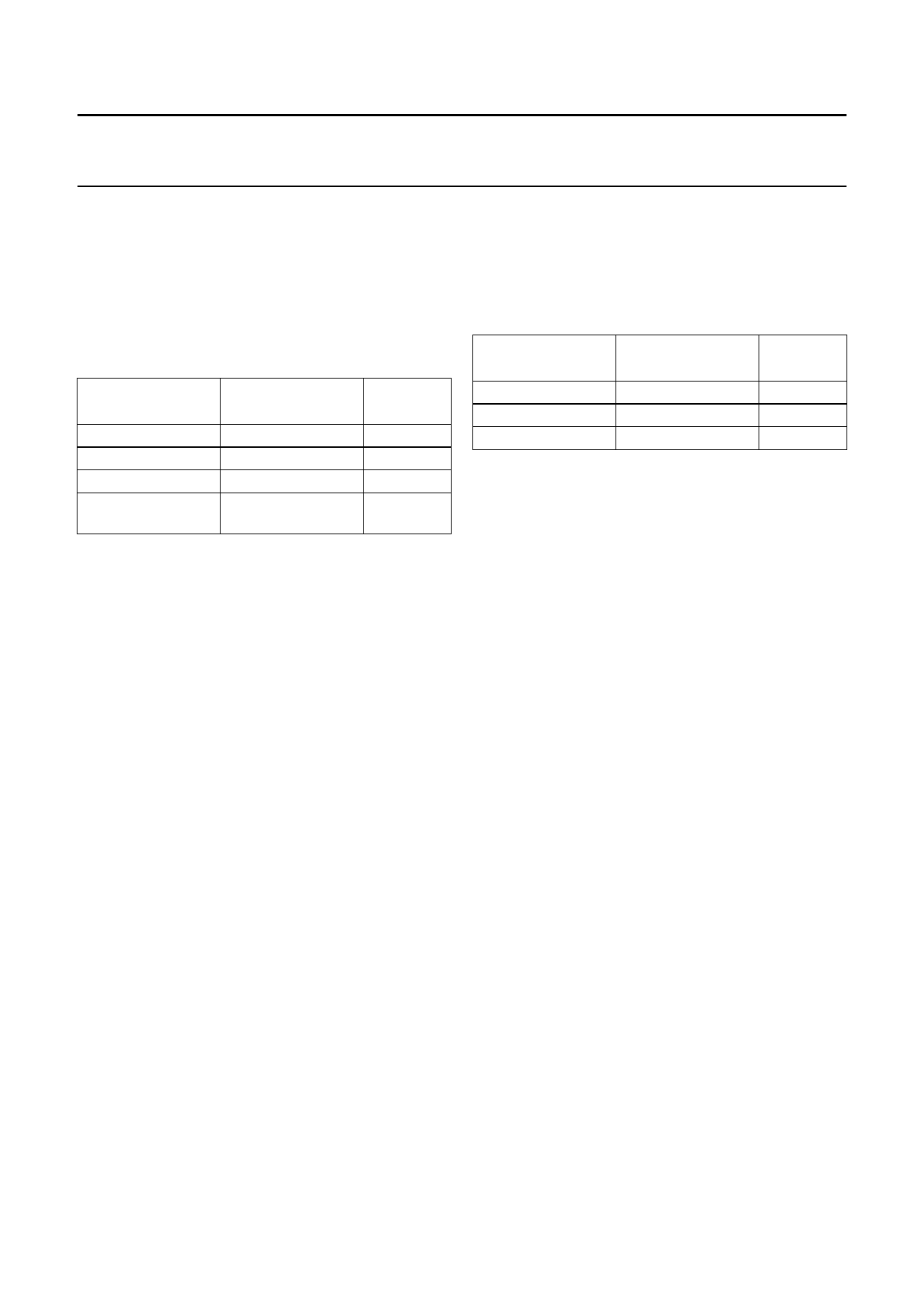
Table 2 Decimation filter characteristics
ITEM
Passband ripple
Stop band
Dynamic range
Overall gain
CONDITIONS
0 to 0.45fs
>0.55fs
0 to 0.45fs
input channel 1;
0 dB input
VALUE
(dB)
±0.05
−60
108
−1.16
7.10 Overload detection (ADC)
This name is convenient but a little inaccurate. In practice
the output is used to indicate whenever that output data, in
either the left or right channel, is bigger than −1 dB (actual
figure is −1.16 dB) of the maximum possible digital swing.
If this condition is detected the OVERFL output is forced
HIGH for at least 512fs cycles (11.6 ms at fs = 44.1 kHz).
This time-out is reset for each infringement.
7.11 Mute (ADC)
On recovery from power-down or switching on of the
system clock, the serial data output on pin DATAO is held
at LOW level until valid data is available from the
decimation filter. This time depends on whether the
DC-cancellation filter is selected:
• DC cancel off:
t
=
1----0---2----4-
fs
;
t
=
23.2
ms
at
fs
=
44.1
kHz
• DC cancel on:
t
=
1----2---2----8---8--
fs
;
t
=
279
ms
at
fs
=
44.1
kHz.
7.12 Interpolation filter (DAC)
The digital filter interpolates from 1fs to 128fs by means of
a cascade of a recursive filter and a Finite Impulse
Response (FIR) filter.
Table 3 Interpolation filter characteristics
ITEM
Passband ripple
Stop band
Dynamic range
CONDITIONS
0 to 0.45fs
>0.55fs
0 to 0.45fs
VALUE
(dB)
±0.03
−50
108
7.13 Peak detector
In the playback path a peak level detector is build in.
The position of the peak detection can be set via the
L3-interface to either before or after the sound features.
The peak level detector is implemented as a peak-hold
detector, which means that the highest sound level is hold
until the peak level is read out via the L3-interface. After
read-out the peak level registers are reset.
7.14 Quick mute
A hard mute can be activated via the static pin QMUTE.
When QMUTE is set HIGH, the output signal is instantly
muted to zero. Setting QMUTE to LOW, the mute is
instantly de-activated.
7.15 Noise shaper (DAC)
The 3rd-order noise shaper operates at 128fs. It shifts
in-band quantization noise to frequencies well above the
audio band. This noise shaping technique allows for high
signal-to-noise ratios. The noise shaper output is
converted into an analog signal using a filter stream
digital-to-analog converter.
2002 May 16
8
Share Link: