U2400B Просмотр технического описания (PDF) - Temic Semiconductors
Номер в каталоге
Компоненты Описание
производитель
U2400B Datasheet PDF : 15 Pages
| |||
U2400B
If a DC voltage in the range of 0.9 to 2.1 V is supplied to
comparator positive input (Pin 2), the discharge and
charge outputs are deactivated as soon as the oscillator’s
saw-tooth voltage (Pin 3) exceeds the DC voltage at Pin 2
(figures 9, 10 and 11). This pulse-width modulation
* effects the active discharge and charge output in each
mode discharge, charge or trickle charge. This offers
the possibility of matching the r.m.s. current to various
battery capacities by means of a switchable voltage
divider.
Pin 14 must be connected to reference voltage Pin 7, if
the internal clock signals are derived from the mains
synchronization input Pin 1 with simultaneous pulse-
width modulation. The oscillator can then be used
deviating from 200 Hz.
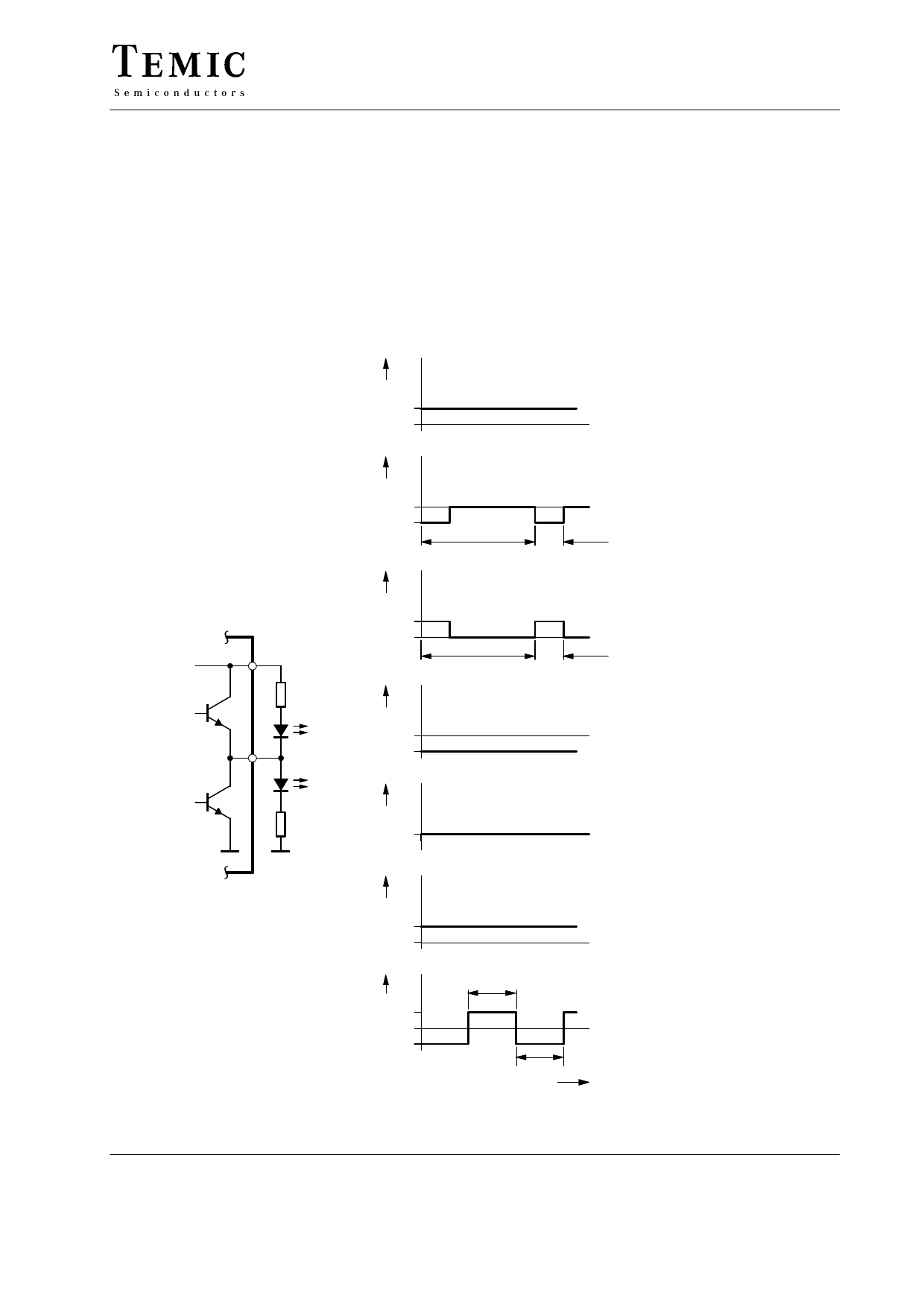
As soon as a battery is removed, the red LED is active
(= no contact). A total pause of approximately 2 seconds
must be given between removing the charged battery and
inserting a new battery to inform the IC that the inserted
battery is to be charged.
mA
I9
10
0
red
No battery contact
mA
I9
green
0
–10
800 ms
green
Charge
200 ms
internal 7
3V
red
9 O9 TLHR 5400
green
mA
I9
10
0 red
mA
I9 0
–10
TLHG 5400
mA
I9
0
800 ms
red
Discharge
200 ms
green
Trickle charge
Stand – by
94 9379
mA
I9
10
0
red
mA
I9 10
0
–10
green
200 ms
red
green
200 ms
t
Figure 5. Status display output
Failure function I
Failure with
charge stop
Failure function II
Expired charge
time with
interruption
TELEFUNKEN Semiconductors
Rev. A2, 21-Nov-96
5 (15)
Share Link: 