TC826CBU Просмотр технического описания (PDF) - TelCom Semiconductor Inc => Microchip
Номер в каталоге
Компоненты Описание
производитель
TC826CBU Datasheet PDF : 12 Pages
| |||
A/D CONVERTER WITH
BAR GRAPH DISPLAY OUTPUT
TC826
The differential input voltage must be within the device
common-mode range when the converter and measured
system share the same power supply common (ground). If
the converter and measured system do not share the same
power supply common, –IN should be tied to analog-com-
mon. This is the usual connection for battery operated
systems. Polarity is determined at the end of signal integrate
signal phase. The sign bit is a true polarity indication in that
signals less than 1 LSB are correctly determined. This
allows precision null detection limited only by device noise
and system noise.
Reference Integrate Cycle
The final phase is reference integrate or deintegrate.
–IN is internally connected to analog common and +IN is
connected with the correct polarity to cause the integrator
output to return to zero. The time required for the output to
return to zero is proportional to the input signal and is
between 0 and 40 counts. The digital reading displayed is:
VI N
20 = VREF
System Timing
The oscillator frequency is divided by 32 prior to clocking
the internal counters. The three phase measurement cycle
takes a total of 80 clock pulses. The 80 count cycle is
independent of input signal magnitude.
Each phase of the measurement cycle has the following
length:
• Auto-Zero Phase: 19 to 59 Counts
For signals less than full-scale the auto-zero is as-
signed the unused reference integrate time period.
• Signal Integrate: 20 Counts
This time period is fixed. The integration period is:
TSI = 20
32
FOSC
Where FOSC is the externally set clock frequency.
• Reference Integrate: 0 to 41 Counts
Reference Voltage Selection
A full-scale reading requires the input signal be twice the
reference voltage. The reference potential is measured
between REF IN (Pin 5) and ANALOG COMMON Pin 2).
Required Full-Scale Voltage
20mV
2V
VREF
10mV
1V
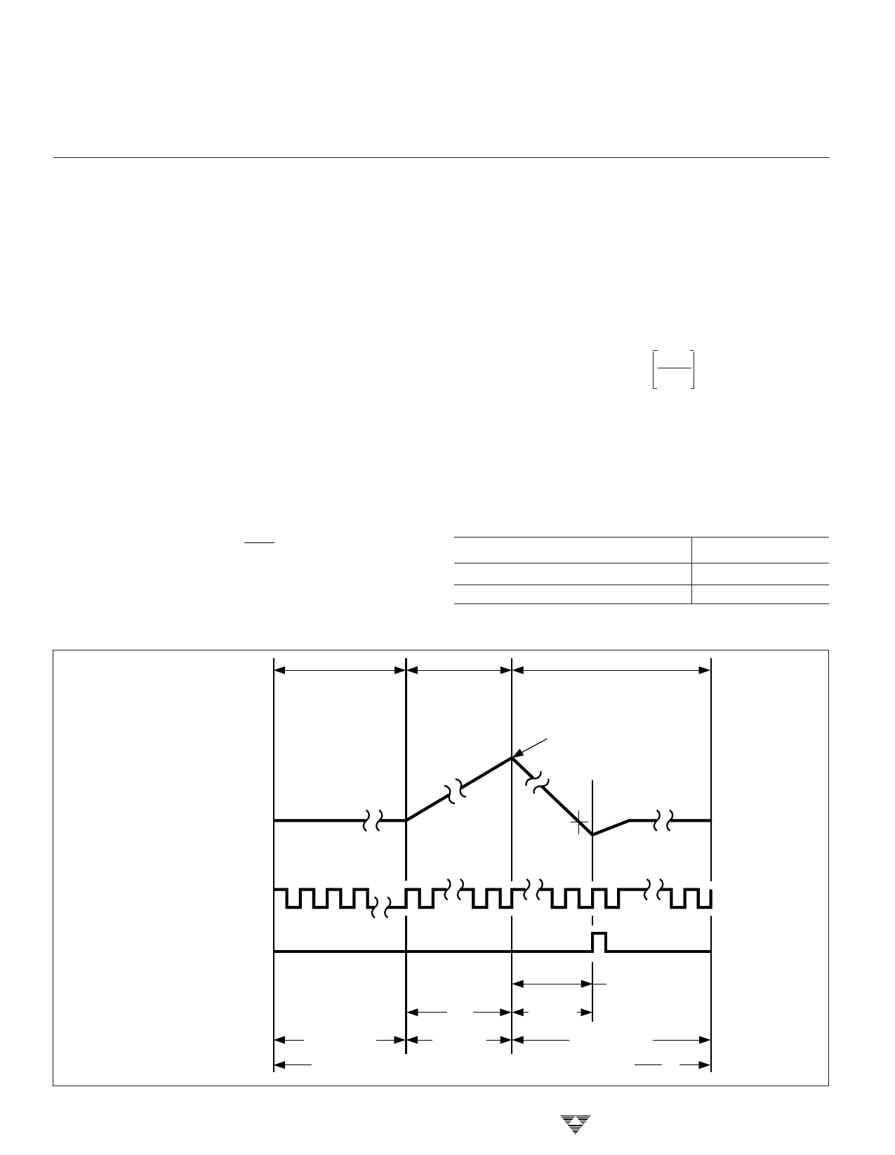
INTEGRATOR
OUTPUT
AUTO–ZERO
PHASE (AZ)
SIGNAL
INTEGRATE
PHASE (SI)
REFERENCE INTEGRATE
PHASE (RI)
(DEINTEGRATE)
SIGN BIT
DETERMINED
3-178
ANALOG
COMMON
POTENTIAL
INTERNAL
SYSTEM CLOCK
(FSYS)
INTERNAL DATA
LATCH UPDATE
SIGNAL
TRUE ZERO
CROSSING ZERO CROSSING
DETECTED
NUMBER OF
COUNTS
PROPORTIONAL
TI
TD ≈ VIN
TO VIN
19 COUNTS
20
41 COUNTS
MINIMUM
COUNTS
MAXIMUM
1
ONE CONVERSION CYCLE = 80 COUNTS ( TCONV = 80 X FSYS )
Figure 5. TC826 Conversion Has Three Phases
TELCOM SEMICONDUCTOR, INC.
Share Link: 