TDA1593 Просмотр технического описания (PDF) - Philips Electronics
Номер в каталоге
Компоненты Описание
производитель
TDA1593 Datasheet PDF : 20 Pages
| |||
Philips Semiconductors
IF amplifier/demodulator for
FM car radio receivers
Product specification
TDA1593
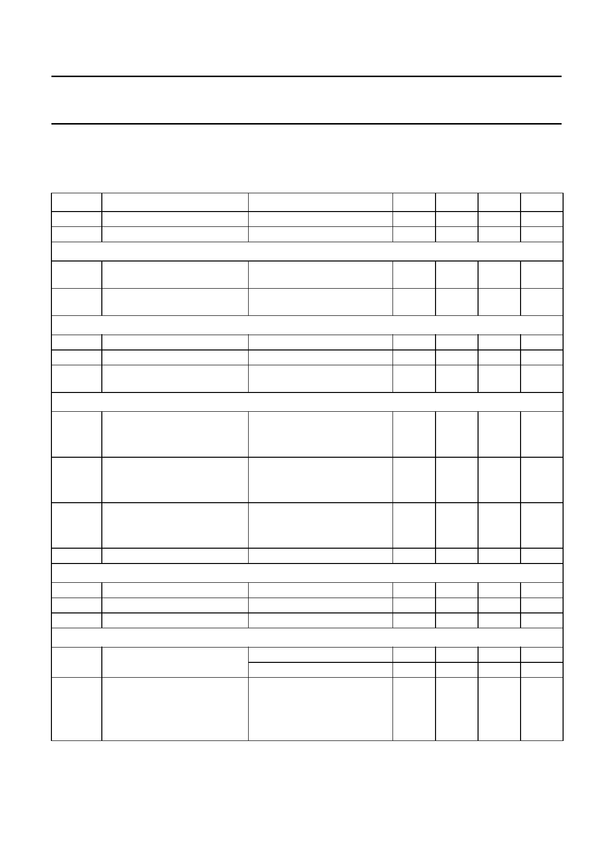
CHARACTERISTICS
VP = 8.5 V; Tamb = +25 °C; fIF = 10.7 MHz; deviation ±22.5 kHz with fm = 400 Hz; Vi = 10 mV (RMS) at pin 20;
de-emphasis of 50 µs; tuned circuit at pins 10 and 11 aligned for symmetrical stop pulses; measurements taken in Fig.4
unless otherwise specified.
SYMBOL
PARAMETER
CONDITIONS
MIN. TYP. MIN. UNIT
VP
supply voltage (pin 1)
IP
supply current
IF amplifier and demodulator
Zi
demodulator input impedance
between pins 10 and 11
Ci
demodulator input capacitance
between pins 10 and 11
I2 = 0
7.5
8.5
12
V
−
20
26
mA
25
40
55
kΩ
−
6
−
pF
AF output (pin 4)
Ro
V4
PSRR
output resistance
DC output level
power supply ripple rejection
(pin 4)
ViIF ≤ 5 µV (RMS) on pin 20
f = 1000 Hz;
Vripple = 50 mV (RMS)
Tuning stop detector
∆fSTOP-0
∆fSTOP-1
V20
V14, 15
detuning frequency for STOP-0
(pin 15)
detuning frequency for STOP-1
(pin 14)
dependency on input voltage for
STOP-0 and STOP-1
(RMS value)
output voltage
see Fig.9
V15 ≥ 3.5 V
V15 ≤ 0.3 V
see Fig.8
V14 ≥ 3.5 V
V14 ≤ 0.3 V
see Fig.7
V14, 15 ≥ 3.5 V
V14, 15 ≤ 0.3 V
I14, 15 = 1 mA
Reference voltage source (pin 5)
Vref
reference output voltage
R5
output resistance
TC
temperature coefficient
I5 = −1 mA
I5 = −1 mA
−
400
2.75 3.1
33
36
−
−
+22.0 −
−
−
−22.0 −
250
−
−
−
−
−
3.3
3.7
−
40
−
3.3
−
Ω
3.45 V
−
dB
+14.0 kHz
−
kHz
−14.0 kHz
−
kHz
−
µV
50
µV
0.3
V
4.1
V
80
Ω
−
mV/K
External muting
V16
muting voltage at I2 = 0
V20 ≤ 5 µV (RMS); see Fig.10 1.45 1.75 2.05 V
V20 = 1 mV (RMS)
3.0
3.45 3.9
V
S
steepness of control voltage
slope: 100 µV ≤ V20 ≤ 100 mV; −
0.85 −
V/dec
20 ∆log V20 = 20 dB
-∆----l∆-o---Vg----1V---6-2---0-
1996 Oct 10
7
Share Link: 