LP62S2048A-T Просмотр технического описания (PDF) - AMIC Technology
Номер в каталоге
Компоненты Описание
производитель
LP62S2048A-T Datasheet PDF : 18 Pages
| |||
LP62S2048A-T Series
Absolute Maximum Ratings*
VCC to GND . . . . . . . .. . . . . . . . . . . . . -0.5V to + 4.6V
IN, IN/OUT Volt to GND . . . . . . . . . -0.5V to VCC + 0.5V
Operating Temperature, Topr . . . . . . . . -25°C to + 85°C
Storage Temperature, Tstg . . .. . . . . . . -55°C to + 125°C
Temperature Under Bias, Tbias .. . . . . . -10°C to + 85°C
Power Dissipation, PT . . . . . . . . . . . . . . . . . . . . . . 0.7W
Soldering Temp. & Time . . . . . . . . . . . . . 260°C, 10 sec
*Comments
Stresses above those listed under "Absolute Maximum
Ratings" may cause permanent damage to this device.
These are stress ratings only. Functional operation of this
device at these or any other conditions above those
indicated in the operational sections of this specification is
not implied or intended. Exposure to the absolute maximum
rating conditions for extended periods may affect device
reliability.
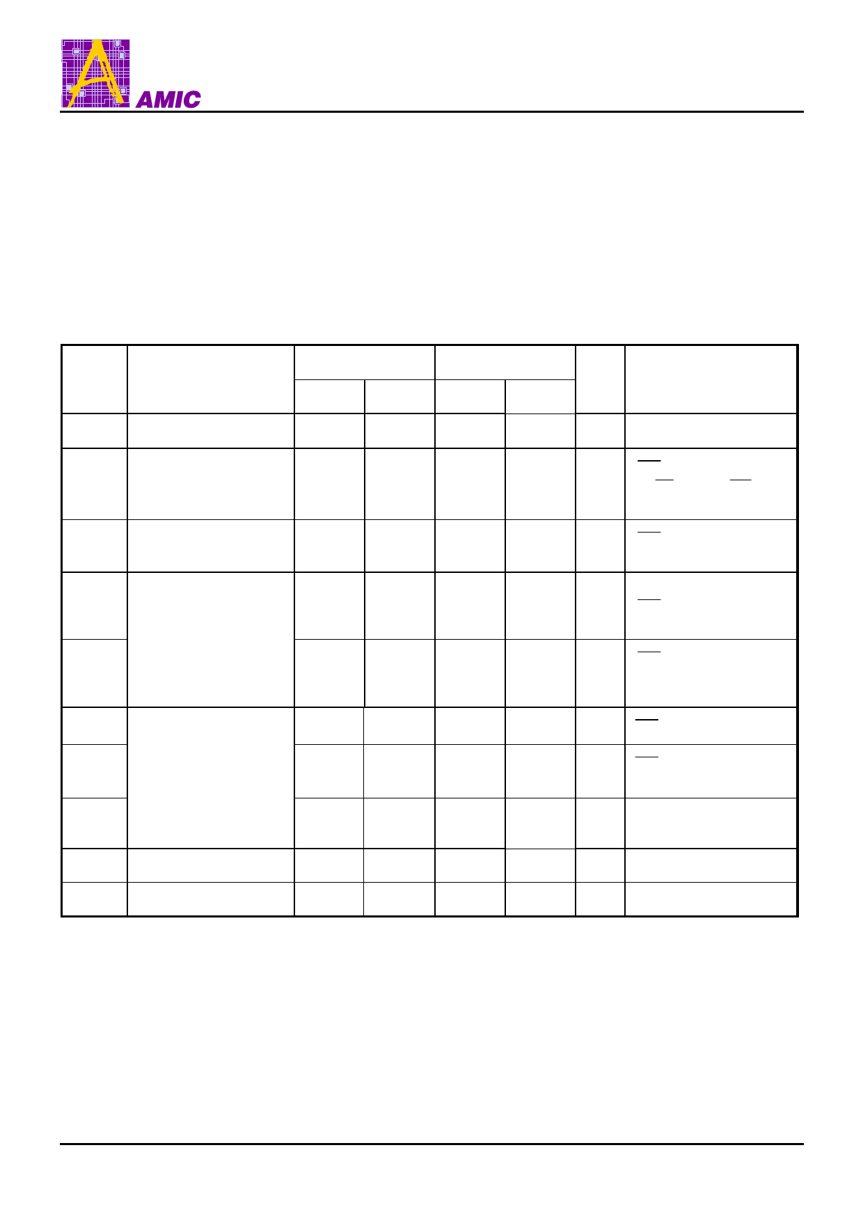
DC Electrical Characteristics (TA = -25°C to + 85°C, VCC = 2.7V to 3.6V, GND = 0V)
Symbol
Parameter
⎜ILI⎥ Input Leakage Current
LP62S2048A-55LLT LP62S2048A-70LLT
Unit
Min.
Max.
Min.
Max.
Conditions
-
1
-
1
µA VIN = GND to VCC
CE1 = VIH or CE2 = VIL
⎜ILO⎥ Output Leakage Current
-
1
-
1
µA or OE = VIH or WE = VIL
VI/O = GND to VCC
Active Power Supply
ICC
Current
-
3
-
3
mA CE1 = VIL, CE2 = VIH
II/O = 0mA
ICC1
Dynamic Operating
Current
ICC2
Min. Cycle, Duty = 100%
-
25
-
20
mA CE1 = VIL, CE2 = VIH
II/O = 0mA
CE1 = VIL, CE2 = VIH
-
5
-
5
mA VIH = VCC, VIL = 0V
f = 1 MHZ, II/O = 0mA
ISB
-
0.5
-
0.5
mA CE1 = VIH or CE2 =VIL
ISB1
Standby Power Supply
Current
-
10
-
CE1 ≥ VCC - 0.2V
10
µA
VIN ≥ 0V
ISB2
-
10
-
10
µA
CE2 ≤ 0.2V
VIN ≥ 0V
VOL
Output Low Voltage
-
0.4
-
0.4
V
IOL = 2.1mA
VOH Output High Voltage
2.2
-
2.2
-
V
IOH = -1.0mA
(August, 2004, Version 1.2)
4
AMIC Technology, Corp.
Share Link: 