MJ410 Просмотр технического описания (PDF) - Motorola => Freescale
Номер в каталоге
Компоненты Описание
производитель
MJ410 Datasheet PDF : 4 Pages
| |||
MJ410
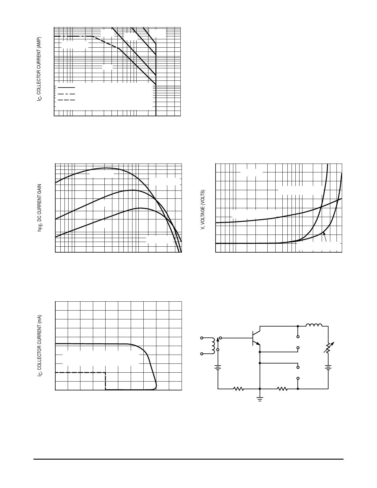
10
5.0
2.0
TJ = 150°C
1.0
0.5
5.0 ms
1.0 ms
500 µs
dc
0.2
0.1
SECONDARY BREAKDOWN LIMITED
0.05
BONDING WIRE LIMITED
THERMAL LIMITATION AT TC = 75°C
0.02
CURVES APPLY BELOW RATED VCEO
0.01
5.0
10
20
50
100
200
500
VCE, COLLECTOR–EMITTER VOLTAGE (VOLTS)
Figure 1. Active Region Safe Operating Area
There are two limitations on the power handling ability of a
transistor: average junction temperature and second break-
down. Safe operating area curves indicate IC – VCE limits of
the transistor that must be observed for reliable operation;
i.e., the transistor must not be subjected to greater dis-
sipation then the curves indicate.
The data of Figure 5 is based on TJ(pk) = 150_C; TC is
v variable depending on conditions. Pulse curves are valid for
duty cycles of 10% provided TJ(pk) 150_C. At high case
temperatures, thermal limitations will reduce the power that
can be handled to values than the limitations imposed by
second breakdown.
100
70
TJ = 150°C
50
VCE = 5.0 Vdc
30
25°C
20
10
7.0
5.0
0.05
– 55°C
TJ = 150°C
0.1
0.2 0.3 0.5
1.0 2.0 3.0 5.0
IC, COLLECTOR CURRENT (AMP)
Figure 2. DC Current Gain
2.0
TJ = 25°C
1.6
VCE(sat) @ IC/IB = 10
1.2
0.8
VBE(sat) @ IC/IB = 10
0.4
0
0.05
VCE(sat) @ IC/IB = 5
0.1
0.2 0.3 0.5
1.0
2.0 3.0 5.0
IC, COLLECTOR CURRENT (AMP)
Figure 3. ‘‘On” Voltages
500
400
50 mH
300
200
VCEO(sus) IS ACCEPTABLE WHEN
VCE ≥ RATED VCEO AT IC = 100 mA
100
Hg RELAY +
6.0 V
–
X
200 Ω
TO SCOPE
+
50 V
Y
–
0
0
100
200
300
400
500
VCE, COLLECTOR–EMITTER VOLTAGE (VOLTS)
Figure 4. Sustaining Voltage Test Load Line
300 Ω
1.0 Ω
Figure 5. Sustaining Voltage Test Circuit
2
Motorola Bipolar Power Transistor Device Data
Share Link: 