ISL88705 –ü—Ä–æ—Å–º–æ—Ç—Ä —Ç–µ—Ö–Ω–∏—á–µ—Å–∫–æ–≥–æ –æ–ø–∏—Å–∞–Ω–∏—è (PDF) - Intersil
–ù–æ–º–µ—Ä –≤ –∫–∞—Ç–∞–ª–æ–≥–µ
–ö–æ–º–ø–æ–Ω–µ–Ω—Ç—ã –û–ø–∏—Å–∞–Ω–∏–µ
–ø—Ä–æ–∏–∑–≤–æ–¥–∏—Ç–µ–ª—å
ISL88705 Datasheet PDF : 15 Pages
| |||
ISL88705, ISL88706, ISL88707, ISL88708, ISL88716, ISL88813
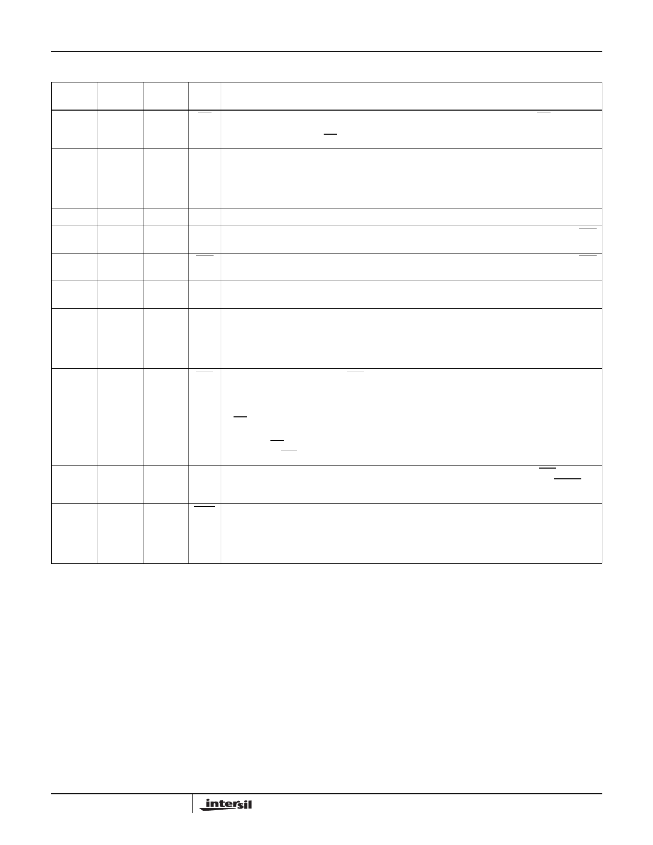
Pin Descriptions
ISL88705, ISL88716, ISL88707,
ISL88706 ISL88813 ISL88708 NAME
DESCRIPTION
1
1
1
MR Manual Reset Input. A reset signal is generated when this input is pulled low. The MR input is an
active low debounced input to which a user can connect a push-button to add manual reset capability
or drive with a signal. The MR pin has an internal 20kΩ pull-up.
2
2
2
VDD Power Supply Terminal. The voltage at this pin is compared against an internal factory-programmed
voltage trip point, VTH1. A reset is first asserted when the device is initially powered up to ensure that
the power supply has stabilized. Thereafter, reset is again asserted whenever VDD falls below VTH1.
The device is designed with hysteresis to help prevent chattering due to noise and is immune to brief
power-supply transients. The voltage threshold VTH1 is specified in the part number suffix.
3
3
3
GND Ground Connection
4
4
4
PFI Power-Fail Input This is an auxiliary monitored voltage input with a 1.25V threshold that causes PFO
state to follow the PFI input state.
5
5
5
PFO Power-Fail Output. This output goes high if the voltage on PFI is greater than 1.25V, otherwise PFO
stays low.
6
CPOR Adjustable POR Time-out Delay Input. Connecting an external capacitor from CPOR to ground
allows the user to increase the Power-On Reset time-out (tPOR) from the nominal 200ms.
6
6
WDI Watchdog Input. The Watchdog Input takes an input from a microprocessor and ensures that it
periodically toggles the WDI pin, otherwise the internal nominal 1.6s watchdog timer runs out, then
reset is asserted and WDO is pulled low. The internal Watchdog Timer is cleared whenever the WDI
sees a rising or falling edge or the device is manually reset. Floating WDI or connecting WDI to a
high-impedance three-state buffer disables the watchdog feature.
7
7
RST Active-Low Reset Output. The RST output is an active low output with an internal PMOS pull-up
that is pulled low to GND when reset is asserted. Reset is asserted whenever:
1. The device is first powered up
2. VDD falls below its minimum voltage sense level or
3. MR is asserted.
The reset output continues to be asserted for typically 200ms after VDD rises above the reset
threshold or MR input goes from low to high. A watchdog time-out will not trigger a reset unless WDO
is connected to MR.
7
8
RST Active-High Reset Output. The RST pin functions identically to its complementary RST output but
is an active high push-pull output. RST is set high to VDD when reset is asserted. See the RST in “Pin
Descriptions” on page 4 for more details on conditions that cause a reset.
8
8
WDO
Watchdog Output. This output is pulled low when the nominal 1.6s internal Watchdog Timer expires
and periodically resets until the watchdog is cleared. WDO also goes low during low VDD conditions.
Whenever VDD is below the reset threshold, WDO stays low. However, unlike RESET, WDO does
not have a minimum pulse width. As soon as VDD rises above the reset threshold, WDO goes high
with no delay.
4
FN8092.5
January 12, 2009
Share Link: 