UC3842 Просмотр технического описания (PDF) - Philips Electronics
Номер в каталоге
Компоненты Описание
производитель
UC3842 Datasheet PDF : 8 Pages
| |||
Philips Semiconductors Linear Products
Current-mode PWM controller
Product specification
UC3842
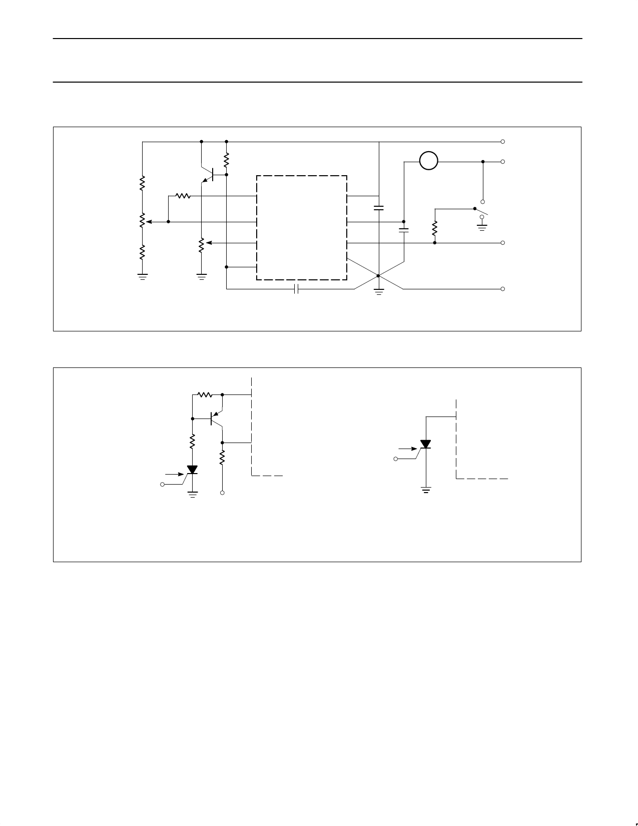
OPEN-LOOP LABORATORY TEST FIXTURE
VREF
RT
A
2N2222
4.7k
100k
1
UC3842
8
COMP
VREF
0.1µF
VCC
ERROR AMP
ADJUST
4.7k
5k
ISENSE
ADJUST
2
VFB
3
ISENSE
4
RT/CT
7
VCC
6
OUTPUT
5
GND
0.1µF 1k
1W
OUTPUT
GND
CT
NOTE:
High peak currents associated with capacitive loads necessitate careful grounding techniques. Timing and bypass capacitors should be connected close to Pin 5 in a single point
ground. The transistor and 5k potentiometer are used to sample the oscillator waveform and apply an adjustable ramp to Pin 3.
SHUTDOWN TECHNIQUES
4.7k
8
4.7k
SHUTDOWN
3
ISENSE
500
SHUTDOWN
1
COMP
TO CURRENT
SENSE RESISTOR
NOTE:
Shutdown of the UC3842 can be accomplished by two methods; either raise Pin 3 above 1V or pull Pin 1 below a voltage two diode drops above ground. Either method causes the
output of the PWM comparator to be high (refer to Block Diagram). The PWM latch is reset dominant so that the output will remain low until the next clock cycle after the shutdown
condition at Pins 1 and/or 3 is removed. In the examples shown, an externally-latched shutdown may be accomplished by adding an SCR which will be reset by cycling
VCC below the lower UVLO threshold (10V). At this point all internal bias is removed, allowing the SCR to reset.
August 31, 1994
1105
Share Link: 