UC3842 Просмотр технического описания (PDF) - Philips Electronics
Номер в каталоге
Компоненты Описание
производитель
UC3842 Datasheet PDF : 8 Pages
| |||
Philips Semiconductors Linear Products
Current-mode PWM controller
Product specification
UC3842
DC AND AC ELECTRICAL CHARACTERISTICS
0≤TJ≤70°C for UC3842; VCC=154; RT=10kΩ; CT=3.3nF, unless otherwise specified
SYMBOL
PARAMETER
TEST CONDITIONS
Output section
VOL
Output Low-Level
VOH
Output High-Level
tR
Rise time
tF
Fall time
Undervoltage lockout section
ISINK=20mA
ISINK=200mA
ISOURCE=20mA
ISOURCE=200mA
CL=1nF
CL=1nF
Start threshold
Min. operating voltage after turn on
PWM section
Maximum duty cycle
Minimum duty cycle
Total standby current
Start-up current
ICC
Operating supply current
VCC zener voltage
Maximum operating frequency section
VPIN 2=VPIN 3=0V
ICC=25mA
Maximum operating frequency for all
functions operating cycle-by-cycle
NOTES:
1. These parameters, although guaranteed, are not 100% tested in production.
2. Parameter measured at trip point of latch with VPIN 2=0.
3.
Gain defined as:
A
+
DVPIN 1
DVPIN 3
;
0 v VPIN 3
v 0.8V
UC3842
Min Typ Max
UNIT
0.1 0.4
V
1.5 2.2
13 13.5
V
12 13.5
50 150
ns
50 150
ns
14.5 16 17.5
V
8.5 10 11.5
V
93 97 100
%
0
0.5 1
mA
11 17
mA
34
V
400
kHz
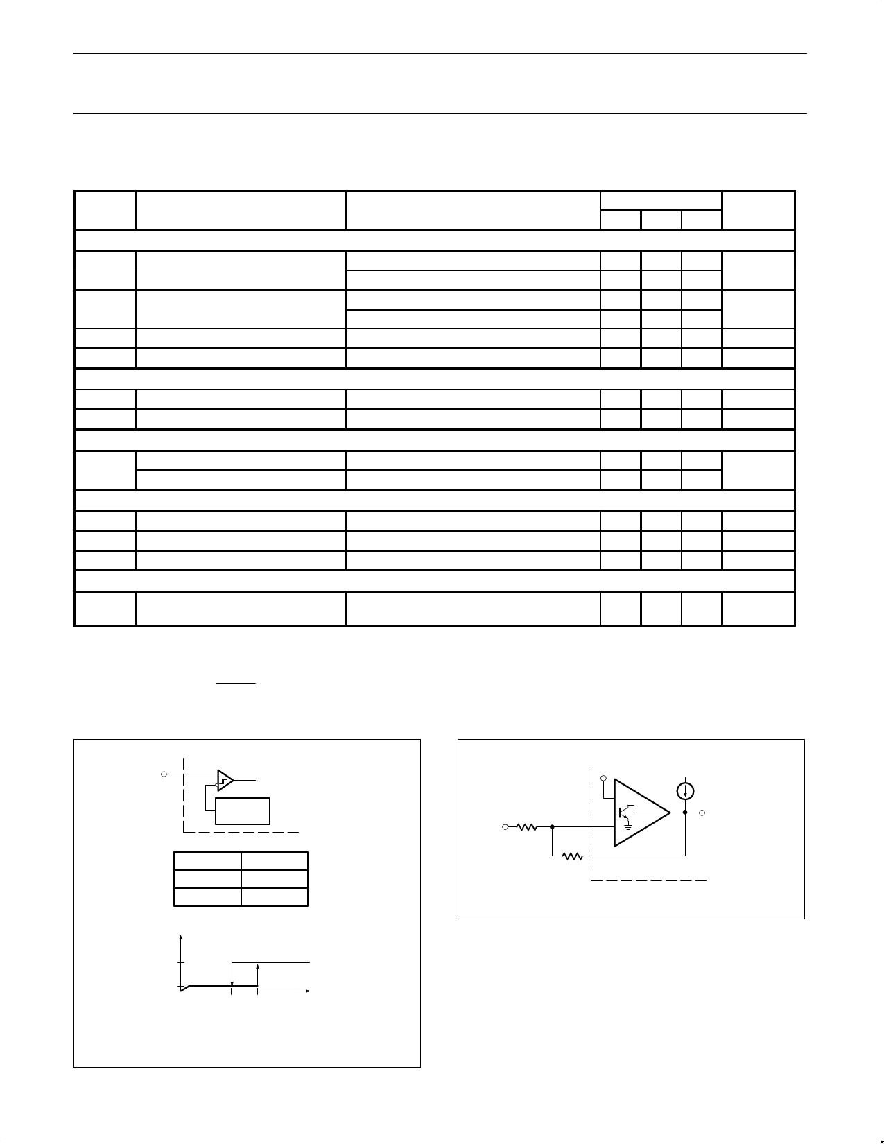
UNDERVOLTAGE LOCKOUT
ERROR AMP CONFIGURATION
7
VCC
ON/OFF COMMAND
TO REST OF IC
VON
VOFF
ICC
UC3842
16V
10V
2.5V
+
ZI
2
–
VFB
1
COMP
NOTE:
Error AMP can source or sink up to 0.5mA.
0.5mA
<15mA
<1mA
VOFF VON
VCC
NOTE:
During Undervoltage Lock-Out, the output driver is biased to a high
impedance state. Pin 6 should be shunted to ground with a bleeder
resistor to prevent activating the power switch with output leakage current.
August 31, 1994
1103
Share Link: 