MAEH121575ADA Просмотр технического описания (PDF) - Systemsensor advanced ideas.
Номер в каталоге
Компоненты Описание
производитель
MAEH121575ADA Datasheet PDF : 4 Pages
| |||
Engineering Specifications
Strobe shall be a System Sensor Model ______ listed to
Standard UL 1971 for the Hearing Impaired and shall be
approved for Fire Protective Service. Strobe shall be wired
as a Primary Signaling Notification appliance. Strobe shall
also comply with the Americans with Disabilities Act
requirements for visible signaling appliances. Strobe shall
operate on 12 or 24VDC from a regulated DC supply or
full-wave rectified, unfiltered supply. The signaling strobe
shall be powered from a non-coded power supply when
powered with the horn or powered independently. Strobe
shall have no measurable in-rush current in excess of
operating peak current. Visual signaling devices are to be
installed in all non-sleeping/corridor and sleeping areas
per plans and specifications. The strobe light shall consist
of a xenon flash tube and associated lens/reflector system.
All strobes shall be capable of mounting to a standard 4″ ×
4″ × 11/2″ backbox, in either a surface mount or semiflush
mount with separate mounting plate.
Sound Output Selection Guide
Multi-Alert Sounder – MA12/24D
Clips on
Available Sounds
Tabs (ABC)1
Slow Whoop
ABC
800 Hz continuous
(factory setting)
BC
800–1000 Hz Alternating
AC
2400 Interrupted
AB
2400 Continuous
C
1200 Interrupted
B
Swept Frequency
A
Fast Warble
None
Current (mA)
DC Regulated/FWR Unfiltered2
12V
24V
30V
21/40 38/56 46/72
15/24
17/32
19/23
21/31
13/19
17/24
15/27
28/45
34/46
35/56
38/59
23/33
34/47
30/47
35/55
43/58
43/64
46/73
27/41
43/60
38/59
Average*
12V
24V
85
92
Sound Output (dBA)
Peak*
12V
24V
93
100
UL (dBA) Ratings
12V
24V
79
85
87
93
94
99
79
85
85
92
91
98
79
85
89
90
96
98
79
85
85
94
93
104
79
85
85
91
95
101
75
82
85
92
96
101
79
85
85
92
93
100
79
85
Multi-Alert Sounder – MA12/24EH
Current (mA)
Sound Output (dBA)
Clips on
DC Regulated/FWR Unfiltered2
Average*
Peak*
UL (dBA) Ratings
Available Sounds
Tabs (ABC)1
12V
24V
30V
12V
24V
12V
24V
12V
24V
Fast Whoop
ABC
21/40 38/56 46/72
85
92
93
100
79
85
800 Hz Continuous
BC
15/24 28/45 35/55
87
93
96
101
79
85
800/1000 Hz Fast Dual
AC
17/32 34/46 43/58
85
92
95
101
79
85
Chirp
AB
19/23 35/56 43/64
89
90
93
104
79
85
2400 Hz Continuous
C
21/31 38/59 46/73
85
94
96
98
79
85
Bell
B
13/19 23/33 27/41
85
91
91
98
75
82
Laser
A
17/24 34/47 43/60
85
92
94
99
79
85
Electro-Mechanical
None
15/27 30/47 38/59
85
92
93
100
79
85
(factory setting)
* dBA measured in anechoic room at 10 feet.
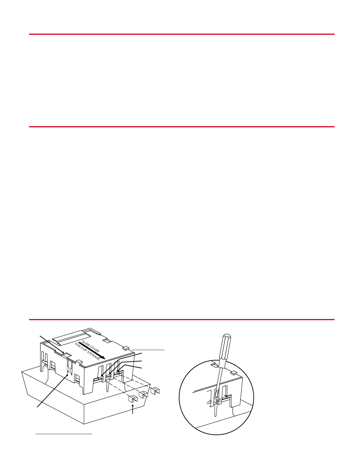
1.See Tone Selection diagram below for tab clip removal and storage.
2.All models can be powered using uncoded full wave rectified, unfiltered supplies. Under no circumstances can the MA12/24 or SS12/24 Series device input
voltage exceed 33 VDC or be less than 9.6 VDC.
MA Sounder Tone Selection
COVER SLOT
FOR CSLLIPIDSETCOORVAEGRE
TONE
SELECTION TABS
TAB A
TAB B
TAB C
CLIP
STORAGE
FOR STORING UNUSED CLIPS:
SLIDE COVER BACK TO ALIGN COVER SLOT
WITH CLIP STORAGE POST.
Page 2
CLIPS REMOVED OR
ADDED TO SELECT
DESIRED TONE.
USE A
SMALL-
BLADED
SCREWDRIVER
TO REMOVE
CLIPS
A05-206-04
Share Link: 