SRF1040(Old_V) Просмотр технического описания (PDF) - TSC Corporation
Номер в каталоге
Компоненты Описание
производитель
SRF1040 Datasheet PDF : 2 Pages
| |||
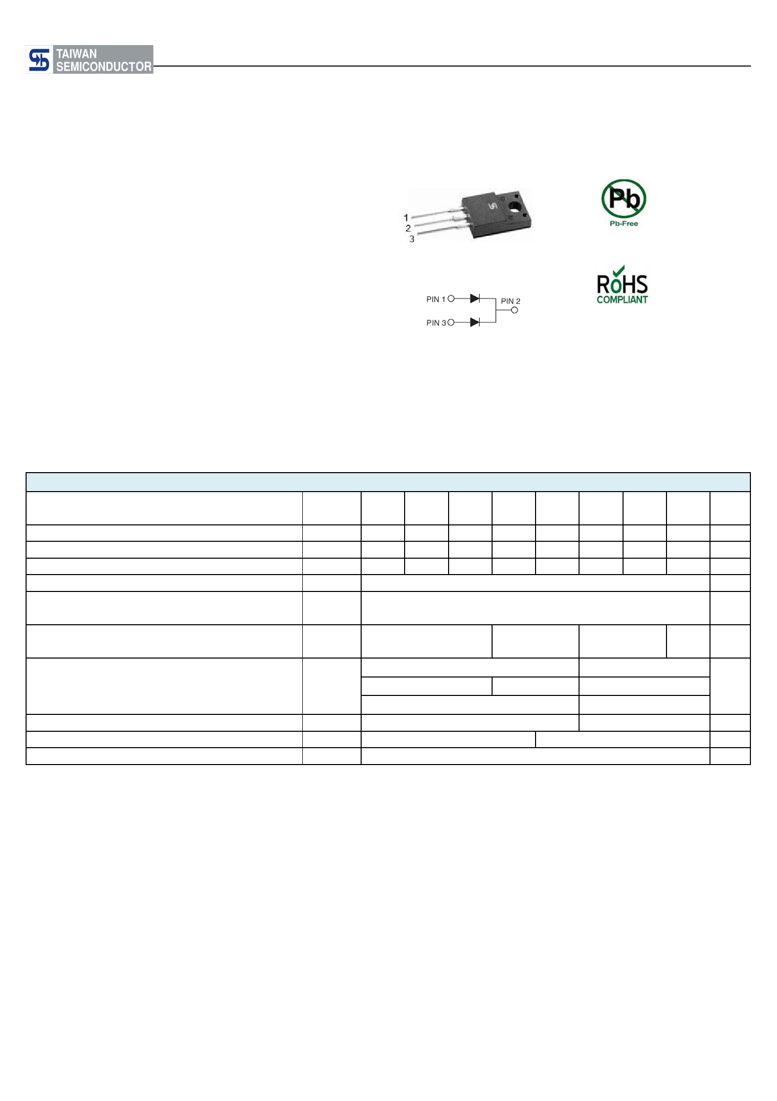
SRF1020 THRU SRF10100
Features
Isolation 10.0 AMPS. Schottky Barrier Rectifiers
Voltage Range
20 to 100 Volts
Current
10.0 Amperes
ITO-220AB
Low forward voltage drop
High current capability
High reliability
High surge current capability
Mechanical Data
.185(4.7)
.173(4.4)
.124(3.16)
. 11 8 ( 3 . 0 )
.406(10.3)
.390(9.90)
.134(3.4)DIA
.113(3.0)DIA
.272(6.9)
.248(6.3)
.112(2.85)
.100(2.55)
.606(15.5)
.583(14.8)
Cases: ITO-220AB molded plastic
Epoxy: UL 94V-O rate flame retardant
Terminals: Leads solderable per MIL-
STD-202, Method 208 guaranteed
Polarity: As marked
High temperature soldering guaranteed:
260OC/10 seconds .25”,(6.35mm) from
case.
Weight: 2.24 grams
Mounting torque: 5 in – 1bs. max.
.110(2.8)
.098(2.5)
.030(0.76)
.020(0.50)
.055(1.4)
.043(1.1)
.035(0.9)
.020(0.5)
.161(4.1)
.146(3.7)
.543(13.8)
.512(13.2)
PIN 1
PIN 3
PIN 2
.106(2.7)
.094(2.4)
.106(2.7)
.094(2.4)
Dimensions in inches and (millimeters)
Maximum Ratings and Electrical Characteristics
Rating at 25℃ambient temperature unless otherwise specified.
Single phase, half wave, 60 Hz, resistive or inductive load.
For capacitive load, derate current by 20%
Type Number
Symbol SRF SRF SRF SRF SRF SRF Units
1020 1030 1040 1050 1060 10100
Maximum Recurrent Peak Reverse Voltage
VRRM
20 30 40 50 60 100
V
Maximum RMS Voltage
VRMS
14 21 28 35 42 70
V
Maximum DC Blocking Voltage
VDC
20 30 40 50 60 100 V
Maximum Average Forward Rectified Current
See Fig. 1
I(AV)
10.0
A
Peak Forward Surge Current, 8.3 ms Single
Half Sine-wave Superimposed on Rated
IFSM
Load (JEDEC method )
175
A
Maximum Instantaneous Forward Voltage
@5.0A
Maximum D.C. Reverse Current @ Tc=25℃
at Rated DC Blocking Voltage @ Tc=100℃
Typical Thermal Resistance (Note 1)
VF
IR
RθJC
0.55
0.70
0.5
50
3.5
0.90 V
mA
mA
4.0 ℃/W
Typical Junction Capacitance (Note 2)
Cj
300
pF
Operating Junction Temperature Range
TJ
-65 to +125
-65 to +150
℃
Storage Temperature Range
TSTG
-65 to +150
℃
Notes: 1 Mounted on Heatsink Size of 2 in x 3 in x 0.25 in Al-Plate.
2. Measured at 1MHz and Applied Reverse Voltage of 4.0V D.C.
- 102 -
Share Link: 