SR12 –ü—Ä–æ—Å–º–æ—Ç—Ä —Ç–µ—Ö–Ω–∏—á–µ—Å–∫–æ–≥–æ –æ–ø–∏—Å–∞–Ω–∏—è (PDF) - Semtech Corporation
–ù–æ–º–µ—Ä –≤ –∫–∞—Ç–∞–ª–æ–≥–µ
–ö–æ–º–ø–æ–Ω–µ–Ω—Ç—ã –û–ø–∏—Å–∞–Ω–∏–µ
–ø—Ä–æ–∏–∑–≤–æ–¥–∏—Ç–µ–ª—å
SR12 Datasheet PDF : 8 Pages
| |||
SR12
PROTECTION PRODUCTS
Applications Information
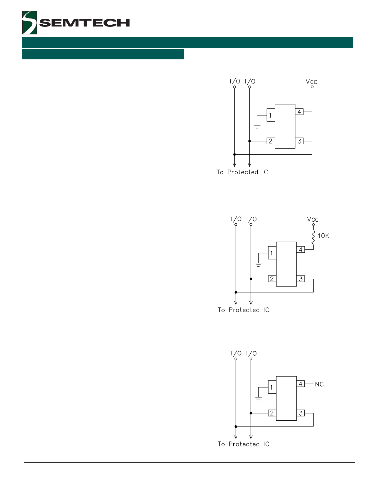
Device Connection Options for Protection of Two
High-Speed Data Lines
Data Line and Power Supply Protection Using Vcc as
reference
The SR12 TVS is designed to protect two data lines from
transient over-voltages by clamping them to a fixed
reference. When the voltage on the protected line
exceeds the reference voltage (plus diode VF) the steering
diodes are forward biased, conducting the transient
current away from the sensitive circuitry.
Data lines are connected at pins 2 and 3. The nega-
tive reference (REF1) is connected at pin 1. This pin
should be connected directly to a ground plane on the
board for best results. The path length is kept as short
as possible to minimize parasitic inductance.
The positive reference (REF2) is connected at pin 4.
The options for connecting the positive reference are
as follows:
1. To protect data lines and the power line, connect
pin 4 directly to the positive supply rail (VCC). In this
configuration the data lines are referenced to the
supply voltage. The internal TVS diode prevents
over-voltage on the supply rail.
2. The SR12 can be isolated from the power supply by
adding a series resistor between pin 4 and VCC. A
value of 10kΩ is recommended. The internal TVS
and steering diodes remain biased, providing the
advantage of lower capacitance.
3. In applications where no positive supply reference
is available, or complete supply isolation is desired,
the internal TVS may be used as the reference. In
this case, pin 4 is not connected. The steering
diodes will begin to conduct when the voltage on
the protected line exceeds the working voltage of
the TVS (plus one diode drop).
Data Line Protection with Bias and Power Supply
Isolation Resistor
Data Line Protection Using Internal TVS Diode as
Reference
ESD Protection With RailClamps
RailClamps are optimized for ESD protection using the
rail-to-rail topology. Along with good board layout,
these devices virtually eliminate the disadvantages of
using discrete components to implement this topology.
Consider the situation shown in Figure 1 where dis-
crete diodes or diode arrays are configured for rail-to-
rail protection on a high speed line. During positive
duration ESD events, the top diode will be forward
biased when the voltage on the protected line exceeds
the reference voltage plus the VF drop of the diode.
 2005 Semtech Corp.
4
www.semtech.com
Share Link: 