B320 Просмотр технического описания (PDF) - Monolithic Power Systems
Номер в каталоге
Компоненты Описание
производитель
B320 Datasheet PDF : 11 Pages
| |||
MP1591 – 2A, 32V, 330KHz STEP-DOWN CONVERTER
The input capacitor value should be greater
than 10µF. The capacitor can be electrolytic,
tantalum or ceramic. However, since it absorbs
the input switching current it requires an
adequate ripple current rating. Its RMS current
rating should be greater than approximately 1/2
of the DC load current.
For insuring stable operation C1 should be
placed as close to the IC as possible.
Alternately, a smaller high quality ceramic
0.1µF capacitor may be placed closer to the IC
and a larger capacitor placed farther away. If
using this technique, it is recommended that the
larger capacitor be a tantalum or electrolytic
type. All ceramic capacitors should be placed
close to the MP1591.
Output Capacitor (C5)
The output capacitor is required to maintain the
DC output voltage. Low ESR capacitors are
preferred to keep the output voltage ripple low.
The characteristics of the output capacitor also
affect the stability of the regulation control
system. Ceramic, tantalum or low ESR
electrolytic capacitors are recommended. In the
case of ceramic capacitors, the impedance at
the switching frequency is dominated by the
capacitance, and so the output voltage ripple is
mostly independent of the ESR. The output
voltage ripple is estimated to be:
VRIPPLE
≅
1.4
×
VIN
×
⎜⎜⎝⎛
fLC
fSW
⎟⎟⎠⎞ 2
Where VRIPPLE is the output ripple voltage, fLC is
the resonant frequency of the LC filter, fSW is the
switching frequency.
In the case of tantalum or low-ESR electrolytic
capacitors, the ESR dominates the impedance
at the switching frequency, and so the output
ripple is calculated as:
VRIPPLE ≅ ∆I × RESR
Where VRIPPLE is the output voltage ripple and
RESR is the equivalent series resistance of the
output capacitors.
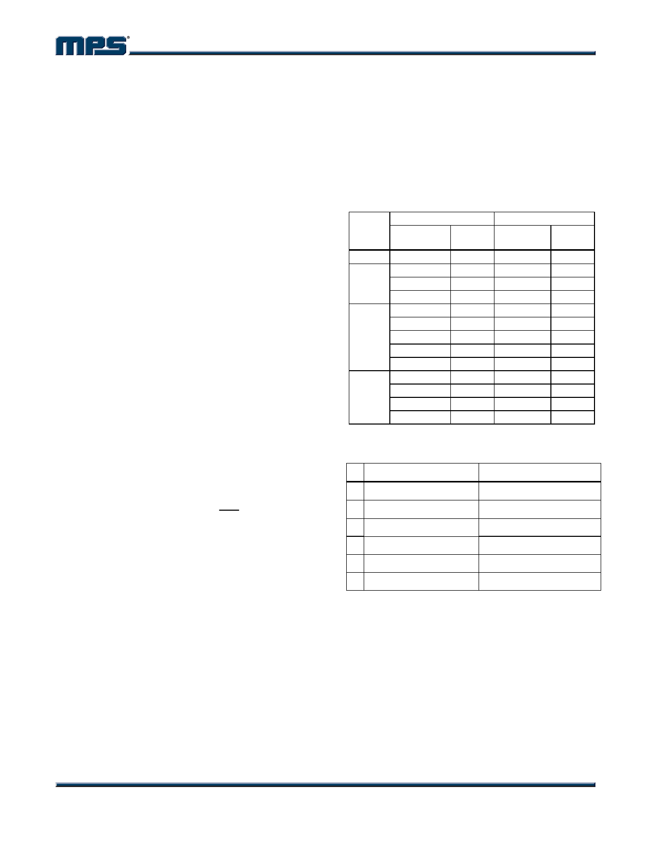
Output Rectifier Diode (D1)
The output rectifier diode supplies the current to
the inductor when the high-side switch is off. To
reduce losses due to the diode forward voltage
and recovery times, use a Schottky rectifier.
Table 2 provides some recommended Schottky
rectifiers based on the maximum input voltage
and current rating.
VIN
(Max)
15V
20V
30V
34V
Table 2—Diode Selection Guide
2A Load Current
3A Load Current
Part
Number
Vendor
Part
Number
Vendor
30BQ15
4
B220
1
B320
1
SK23
6
SK33
1, 6
SR22
6
SS32
3
20BQ030
4
B330
1
B230
1
B340L
1
SK23
6
MBRD330 4, 5
SR23
3, 6
SK33
1, 6
SS23
2, 3
SS33
2, 3
21DQ04
4
B340L
1
MBRS240L
5
MBRS340
4
SK24
6
SK34
1, 6
SS24
2, 3
SS34
2, 3
Table 3 lists manufacturer’s websites.
Table 3—Schottky Diode Manufacturers
# Vendor
Web Site
1 Diodes, Inc.
www.diodes.com
2 Fairchild Semiconductor www.fairchildsemi.com
3 General Semiconductor www.gensemi.com
4 International Rectifier www.irf.com
5 On Semiconductor
www.onsemi.com
6 Pan Jit International
www.panjit.com.tw
Choose a rectifier whose maximum reverse
voltage rating is greater than the maximum
input voltage, and whose current rating is
greater than the maximum load current.
MP1591 Rev. 2.3
www.MonolithicPower.com
6
9/27/2006
MPS Proprietary Information. Unauthorized Photocopy and Duplication Prohibited.
© 2006 MPS. All Rights Reserved.
Share Link: 