SK12 Просмотр технического описания (PDF) - PACELEADER INDUSTRIAL
Номер в каталоге
Компоненты Описание
производитель
SK12 Datasheet PDF : 2 Pages
| |||
SK12 thru SK110
SURFACE MOUNT SCHOTTKY BARRIER RECTIFIER
VOLTAGE - 20 TO 100 VOLTS CURRENT - 1.0 AMPERES
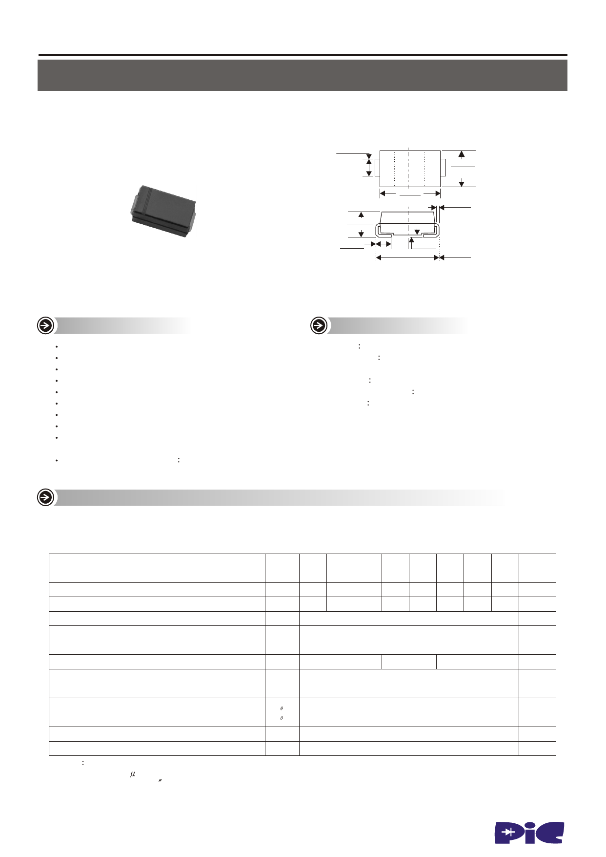
SMA/DO-214AC
.055(1.40)
.062(1.60)
.098(2.50)
.114(2.90)
.078(2.00)
.096(2.44)
.157(4.00)
.181(4.60)
.006(.152)
.012(.305)
.030(0.76)
.060(1.52)
.004(.102)
.008(.203)
.188(4.80)
.208(5.28)
Dimensions in inches and (millimeters)
FEATURES
For surface mount applications
Low profile package
Built-in strain relief
Easy pick and place
Low forward voltage drop
Metal to silicon rectifier, majority carrier conduction
Low power loss, high efficiency
High current and surge capability
Plastic package has Underwriters Laboratory
Flammability Classification 94V-0
High temperature soldering
250oC/10 seconds at terminsls
MECHANICAL DATA
Case JEDEC DO-214AC molded plastic
Terminals Solder plated, solderable per
MIL-STD-202, Method 208
Polarity Color band denotes cathode end
Standard Package 12mm tape (EIA STD EIA-481)
Weight 0.002 ounce, 0.064gram
MAXIMUM RATIXGS AND ELECTRICAL CHARACTERISTICS
Ratings at 25oC ambient temperature unless otherwise specified
Single phase, half wave, 60Hz, resistive or inductive load
For capacitive load, derate current by 20%
SYMBOL SK12 SK13 SK14 SK15 SK16 SK18 SK19 SK110 UNITS
Maximum Repetitive Peak Reverse Voltage
VRRM 20 30 40 50 60 80 90 100 Volts
Maximum RMS Voltage
VRMS 14 21 28 35 42 56 64 71 Volts
Maximum DC Blocking Voltage
VDC 20 30 40 50 60 80 90 100 Volts
Maximum Average Forward Rectified Current at TL (Figure 1) I(AV)
1.0
Amps
Peak Forward Surge Current 8.3ms Single Half Sine-Wave
Superimposed on Rated Load (JEDEC Method)
IFSM
30
Amps
Maximum Instantaneous Forward Voltage at 1.0A
VF
0.5
Maximum DC Reverse Current (NOTE 1) TA=250C
at Rated DC Blocking Voltage TA=1000C
IR
0.7
0.85
Volts
0.5
mA
20
Maximum Thermal Resistance (NOTE 2)
R JA
R JL
Operating Junction Temprature Range
TJ
Storage and Operating Temperature Range
TSTG
NOTES
1. Pulse test with 300 S pulse width, 1% duty cycle
2. P.C.B. mounted on 0.2x0.2 (5.0x5.0mm) copper pad areas
75
17
-55 to +125
-55 to +150
0C / W
0C
0C
www.paceleader.tw
1
Share Link: 