SFH600 –ü—Ä–æ—Å–º–æ—Ç—Ä —Ç–µ—Ö–Ω–∏—á–µ—Å–∫–æ–≥–æ –æ–ø–∏—Å–∞–Ω–∏—è (PDF) - Siemens AG
–ù–æ–º–µ—Ä –≤ –∫–∞—Ç–∞–ª–æ–≥–µ
–ö–æ–º–ø–æ–Ω–µ–Ω—Ç—ã –û–ø–∏—Å–∞–Ω–∏–µ
–ø—Ä–æ–∏–∑–≤–æ–¥–∏—Ç–µ–ª—å
SFH600 Datasheet PDF : 4 Pages
| |||
Current Transfer Ratio and Collector-Emitter Leakage Current
by dash number
-0
-1
-2
-3
Unit
IC/IF at VCE=5 V
(IF=10 mA)
40-80 63-
125
100- 160- %
200
320
IC/IF at VCE=5 V
(IF=1 mA)
30
45
70
90
%
(>13) (>22) (>34) (>56)
Collector-Emitter
Leakage Current 2 (≤
2 (≤
2 (≤
5 (≤
nA
(VCE=10 V)
(ICEO)
35)
35)
35)
70)
Figure 1. Linear operation (without saturation)
IF
RL=75 Ω
IC
VCC=5 V
47 Ω
IF=10 mA, VCC=5 V, TA=25 °C, Typical
Load Resistance
RL
75
Ω
Turn-On Time
tON
3.2
µs
Rise Time
tR
2.0
µs
Turn-Off Time
tOFF
3.0
µs
Fall Time
tf
2.5
µs
Cut-off Frequency
FCO
250
kHz
Figure 2. Switching operation (with saturation)
IF
1 KΩ
VCC=5 V
47 Ω
Typical
Turn-On Time
Rise Time
Turn-Off Time
Fall Time
tON
tR
tOFF
tF
VCESAT
-0
(IF=20 mA)
3.7
2.5
19
11
-1 and -2
(IF=10 mA)
4.5
-3
(IF=5 mA)
5.8
µs
3.0
4.0
µs
21
24
µs
12
14
µs
0.25 (≤0.4)
V
5–2
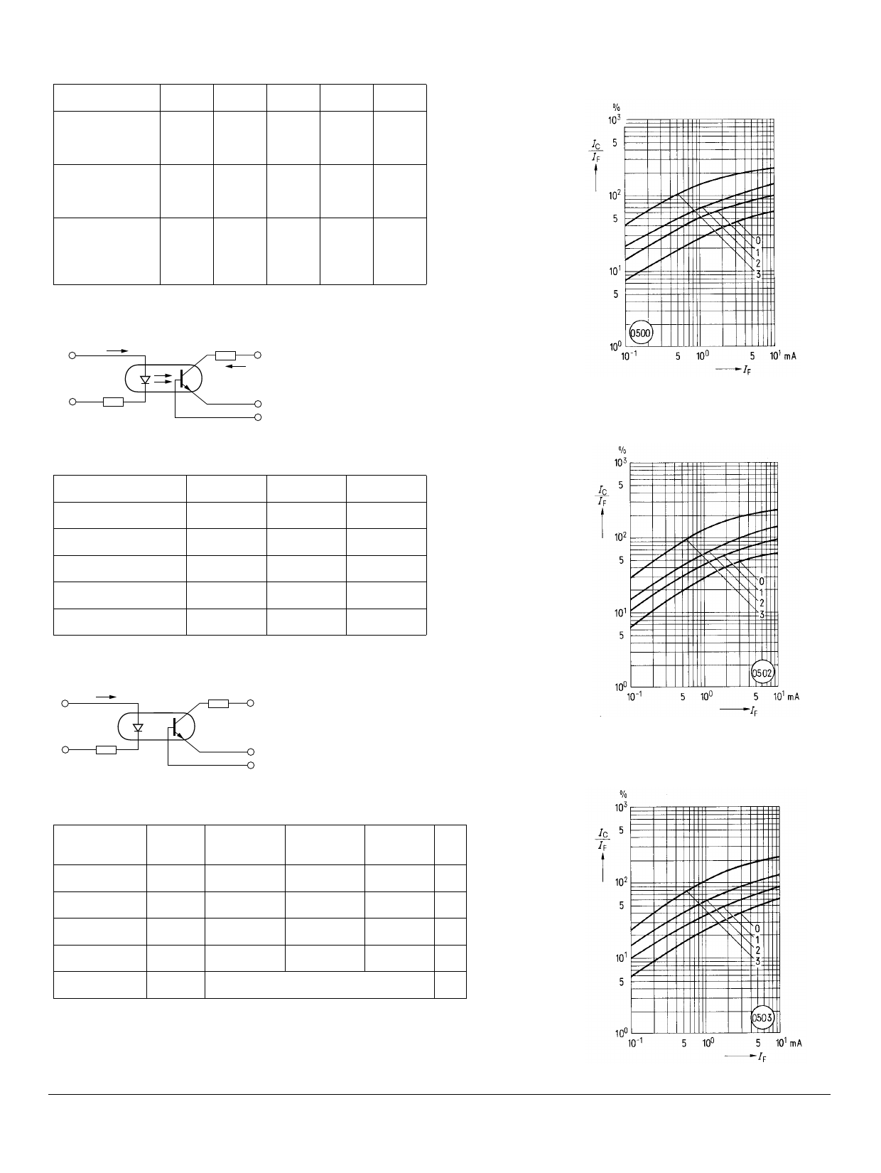
Figure 3. Current transfer ratio versus
diode current
(TA=–25°C, VCE=5 V) IC/IF=f (IF)
Figure 4. Current transfer ratio versus
diode current (TA=0°C, VCE=5 V)
IC/IF=f (IF)
Figure 5. Current transfer ratio versus
diode current (TA=25°C, VCE=5 V)IC/
IF=f (IF)
SFH600
Share Link: 