MC13150FTB Просмотр технического описания (PDF) - LANSDALE Semiconductor Inc.
Номер в каталоге
Компоненты Описание
производитель
MC13150FTB Datasheet PDF : 20 Pages
| |||
ML13150
LANSDALE Semiconductor, Inc.
Legacy Applications Information
EVALUATION PC BOARD
The evaluation PCB is very versatile and is intended to be
used across the entire useful frequency range of this device.
The center section of the board provides an area for attaching
all SMT components to the circuit side and radial leaded
components to the component ground side (see Figures 29
and 30). Additionally, the peripheral area surrounding the RF
core provides pads to add supporting and interface circuitry
as a particular application requires. There is an area dedicated
for a LNA preamp. This evaluation board will be discussed
and referenced in this section.
COMPONENT SELECTION
The evaluation PC board is designed to accommodate specif-
ic components, while also being versatile enough to use com-
ponents from various manufacturers and coil types. The appli-
cations circuit schematic (Figure 15) specifies particular com-
ponents that were used to achieve the results shown in the
typical curves but equivalent components should give similar
results. Component placement views are shown in Figures 27
and 28 for the application circuit in Figure 15 and for the
83.616 MHz crystal oscillator circuit in Figure 16.
INPUT MATCHING COMPONENTS
The input matching circuit shown in the application circuit
schematic (Figure 15) is a series L, shunt C single L section
which is used to match the mixer input to 50 Ω. An alterna-
tive input network may use 1:4 surface mount transformers or
BALUNs. The 12 dB SINAD sensitivity using the 1:4 imped-
ance transformer is typically –100 dBm for fmod = 1.0 kHz
and fdev = ±5.0 kHz at fin = 50 MHz and fLO = 50.455
MHz (see Figure 14).
It is desirable to use a SAW filter before the mixer to provide
additional selectivity an adjacent channel rejection and
improved sensitivity. SAW filters sourced from Toko (Part
#SWS083GBWA) and Murata (Part # SAF83.16MA51X) are
excellent choices to easily interface with the MC13150 mixer.
They are packaged in a 12 pin low profile surface mount
ceramic package. The center frequency is 83.161 MHz and
the 3.0 dB bandwidth is 30 kHz.
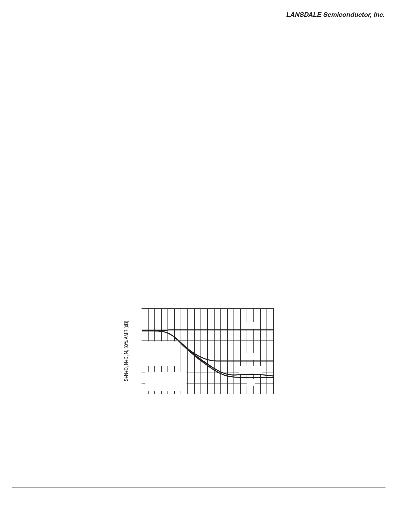
Figure 14. S+N+D, N+D, N, 30% AMR
versus Input Signal Level
20
10
S+N+D
0
–10
VCC = 3.0 Vdc
–20 fmod = 1.0 kHz
fdev = ±5.0 kHz
N+D
–30 fin = 50 MHz
–40 fLO = 50.455 MHz
–50
LO Level = –10 dBm
See Figure 15
30% AMR
N
–60
–120
–100
–80
–60
–40
INPUT SIGNAL (dBm)
Page 8 of 20
www.lansdale.com
Issue A
Share Link: 