MC13150FTA Просмотр технического описания (PDF) - LANSDALE Semiconductor Inc.
Номер в каталоге
Компоненты Описание
производитель
MC13150FTA Datasheet PDF : 20 Pages
| |||
ML13150
LANSDALE Semiconductor, Inc.
Legacy Applications Information
LOCAL OSCILLATORS
HF & VHF APPLICATIONS
In the application schematic, an external sourced local oscilla-
tor is utilized in which the base is biased via a 51 Ω resistor to
VCC. However, the on–chip grounded collector transistor may
be used for HF and VHF local oscillators with higher order
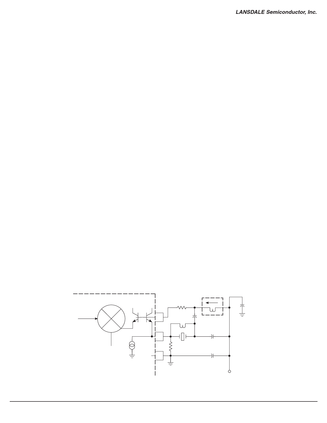
overtone crystals. Figure 16 shows a 5th overtone oscillator at
83.616 MHz. The circuit uses a Butler overtone oscillator con-
figuration. The amplifier is an emitter follower. The crystal is
driven from the emitter and is coupled to the high impedance
base through a capacitive tap network. Operation at the desired
overtone frequency is ensured by the parallel resonant circuit
formed by the variable inductor and the tap capacitors and par-
asitic capacitances of the on–chip transistor and PC board. The
variable inductor specified in the schematic could be replaced
with a high tolerance, high Q ceramic or air wound surface
mount component if the other components have tight enough
tolerance. A variable inductor provides an adjustment for gain
and frequency of the resonant tank ensuring lock up and
start–up of the crystal oscillator. The overtone crystal is chosen
with ESR of typically 80 Ω and 120 Ω maximum; if the resis-
tive loss in the crystal is too high the performance of oscillator
may be impacted by lower gain margins.
A series LC network to ac ground (which is VCC) is com-
prised of the inductance of the base lead of on–chip transistor
and PC board traces and tap capacitors. Parasitic oscillations
often occur in the 200 to 800 MHz range. A small resistor is
placed in series with the base (Pin 28) to cancel the negative
resistance associated with this undesired mode of oscillation.
Since the base input impedance is so large, a small resistor in
the range of 27 to 68 Ω has very little effect on the desired
Butler mode of oscillation.
The crystal parallel capacitance, Co, provides a feedback path
that is low enough in reactance at frequencies of 5th over-
tones or higher to cause trouble. Co has little effect near reso-
nance because of the low impedance of the crystal motional
arm (Rm-Lm-Cm). As the tunable inductor, which forms the
resonant tank with the tap capacitors, is tuned off the crystal
resonant frequency, it may be difficult to tell if the oscillation
is under crystal control. Frequency jumps may occur as the
inductor is tuned. In order to eliminate this behavior an induc-
tor, Lo, is placed in parallel with the crystal. Lo is chosen to
resonant with the crystal parallel capacitance, Co, at the
desired operation frequency. This inductor provides a feed-
back path at frequencies well below resonance; however, the
parallel tank network of the tap capacitors and tunable induc-
tor prevent oscillation at these frequencies.
Figure 16. ML13150 Overtone Oscillator
fRF = 83.16 MHz; fLO = 83.616 MHz
5th Overtone Crystal Oscillator
MC13150
Mixer
28
29
VEE 31
(4)
0.135 µH
33
1.0 µH 39 p
39 p
(3)
27 k 5th OT
XTAL
10 n
+
1.0 µ
VCC
Page 10 of 20
www.lansdale.com
Issue A
Share Link: 