B20200 Просмотр технического описания (PDF) - ON Semiconductor
Номер в каталоге
Компоненты Описание
производитель
B20200 Datasheet PDF : 4 Pages
| |||
MBRF20200CT
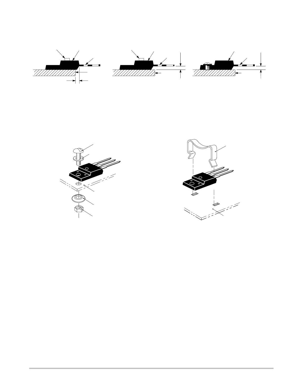
TEST CONDITIONS FOR ISOLATION TESTS*
MOUNTED
CLIP
FULLY ISOLATED
PACKAGE
LEADS
MOUNTED
FULLY ISOLATED
CLIP
PACKAGE
0.107″ MIN
LEADS
MOUNTED
FULLY ISOLATED
PACKAGE
0.107″ MIN
LEADS
HEATSINK
0.110″ MIN
HEATSINK
Figure 3. Clip Mounting Position
for Isolation Test Number 1
Figure 4. Clip Mounting Position
for Isolation Test Number 2
* Measurement made between leads and heatsink with all leads shorted together.
HEATSINK
Figure 5. Screw Mounting Position
for Isolation Test Number 3
MOUNTING INFORMATION**
4-40 SCREW
CLIP
PLAIN WASHER
HEATSINK
COMPRESSION WASHER
NUT
HEATSINK
6a. Screw–Mounted
6b. Clip–Mounted
Figure 6. Typical Mounting Techniques
Laboratory tests on a limited number of samples indicate, when using the screw and compression washer mounting
technique, a screw torque of 6 to 8 in . lbs is sufficient to provide maximum power dissipation capability. The compression
washer helps to maintain a constant pressure on the package over time and during large temperature excursions.
Destructive laboratory tests show that using a hex head 4–40 screw, without washers, and applying a torque in excess of 20
in . lbs will cause the plastic to crack around the mounting hole, resulting in a loss of isolation capability.
Additional tests on slotted 4–40 screws indicate that the screw slot fails between 15 to 20 in . lbs without adversely affecting
the package. However, in order to positively ensure the package integrity of the fully isolated device, ON Semiconductor does
not recommend exceeding 10 in . lbs of mounting torque under any mounting conditions.
**For more information about mounting power semiconductors see Application Note AN1040.
http://onsemi.com
3
Share Link: 