M64285FP Просмотр технического описания (PDF) - MITSUBISHI ELECTRIC
Номер в каталоге
Компоненты Описание
производитель
M64285FP
MITSUBISHI ELECTRIC

M64285FP Datasheet PDF : 26 Pages
| |||
Technical Data Sheet
MITSUBISHI
PRELIMINARY
MITSUBISHI CMOS Image Sensor
M64285FP
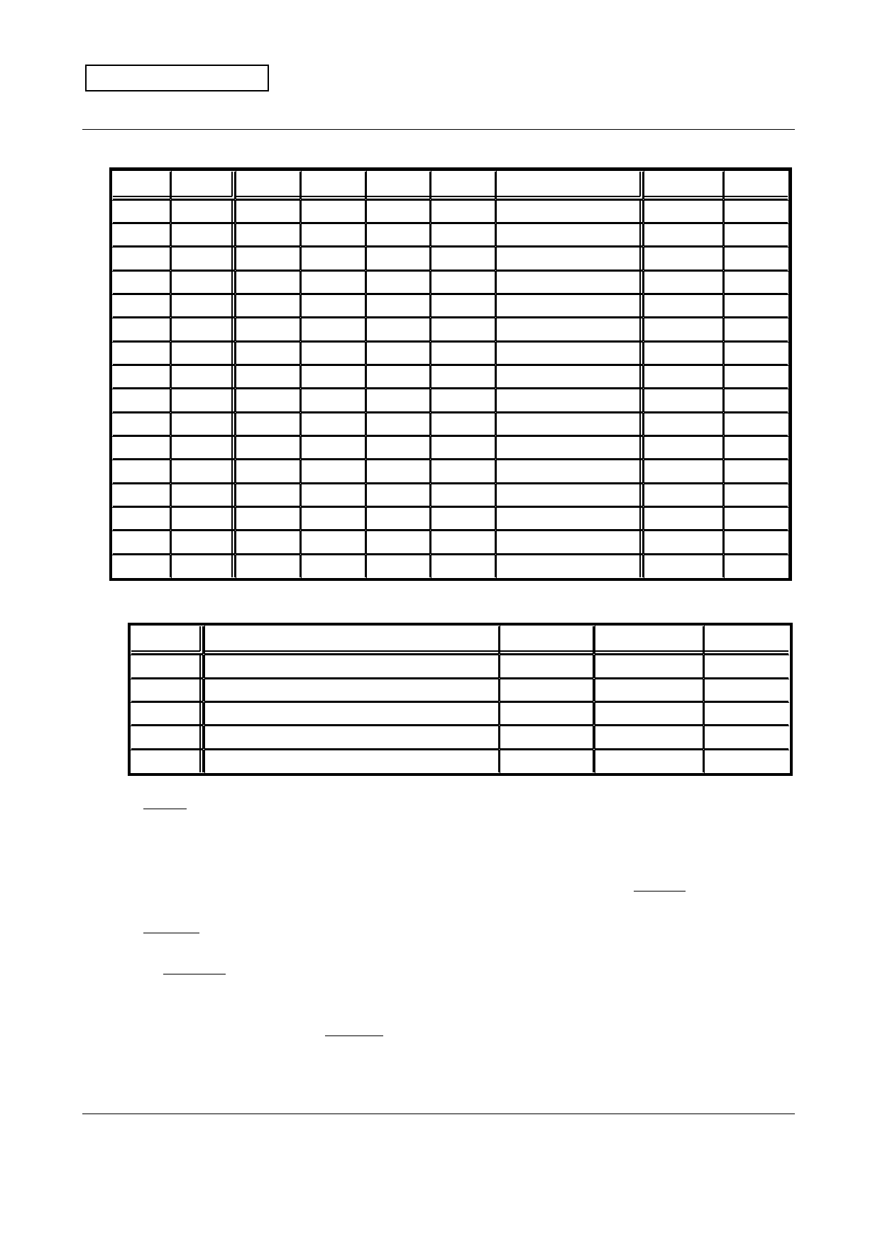
11.2. Register Allocation
No. Address 3
2
1
0
0
0000 MD3 MD2 MD1 MD0
1
0001
0
0
0
0
2
0010
0
0
0
STOP
3
0011 DR3 DR2 DR1 DR0
4
0100
C03
C02
C01
C00
5
0101
C07
C06
C05
C04
6
0110
C11
C10
C09
C08
7
0111
C15
C14
C13
C12
8
1000 GAIN3 GAIN2 GAIN1 GAIN0
9
1001
0
0
OFST4 GAIN4
10
1010
0
0
VREF1 VREF0
11
1011 OFST3 OFST2 OFST1 OFST0
12
1100
0
0 BSTRB STINV
13
1101
0
0
1
0
14
1110
0
0 STDBY POWSV
15
1111
1
1
1
0
Contents
Image capture mode
-
Interrupt setting
Data rate
Accumulation time
Accumulation time
Accumulation time
Accumulation time
Gain
MSB setting
Black level output
Offset subtraction
STRB state
-
Power save mode
-
Reset State cf.
0000
0000
0000
0000
1000
0111
0000
0000
0000
0000
0001
0000
0000
0010
0000
1110
Sec. 11.3
-
Below
Sec. 11.4
Sec. 11.5
Sec. 11.5
Sec. 11.5
Sec. 11.5
Sec. 11.6
-
Sec. 11.7
Sec. 11.8
Below
-
Below
-
Description of the bits of Interrupt setting, STRB state and Power save mode.
Registers
Description
0
1
Reset state
STOP Stop the continuous image capture sequence
Ordinary Stop sequence
0
BSTRB STRB for optical black level output timing
OFF
ON
0
STINV
Invert the STRB signal
Not inverted
Inverted
0
POWSV
Power Save ( AMP current to be 1/10)
OFF
ON
1
STDBY
Standby Mode (AMP current to be cut)
OFF
ON
0
STOP bit forces the chip into Standby state from the continuous image capture state.
When "STOP = 1" is set, image capture sequence stops and the chip falls into the
Standby state, with preserving the register contents. Afterwards, STOP bit is
automatically reset to "0". This bit is allowed to be set in the continuous output modes.
M64285FP can output the inverted STRB signal. If needed, set STINV to "1", else,
set it to "0". M64285FP outputs the optical black level before outputting the image data.
BSTRB selects whether to output the STRB pulse at the optical black level output
timing. If needed to be ON, set BSTRB to "1", else, set it to "0".
POWSV selects the Power Save state, in which power consumption is suppressed by
reducing the AMP current to be 1/10 while the chip is not outputting the analog data
(ex.: just after RESET, or in the accumulation period). The default state for POWSV is
1 (ON). Besides, if the STDBY bit is 1, power consumption is further suppressed by
completely cutting the AMP current while the chip is in the Standby or Halt state.
( 8 / 26 )
Specifications and information herein are subject to change without notice.
02 / 05 / 01
Ver. 2.2E_01
Share Link: