FP2189-PCB2140S Просмотр технического описания (PDF) - Unspecified
Номер в каталоге
Компоненты Описание
производитель
FP2189-PCB2140S Datasheet PDF : 6 Pages
| |||
FP2189
1 Watt HFET
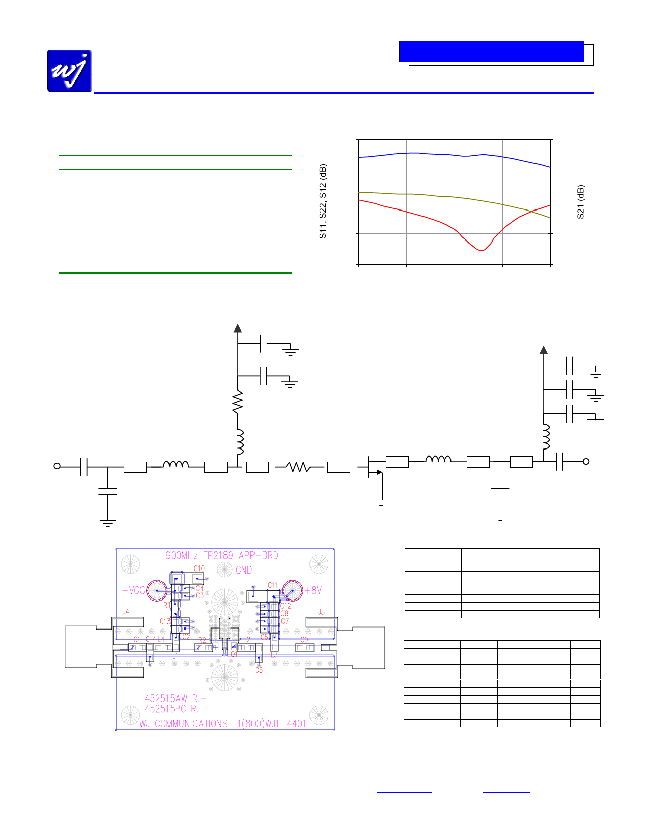
Application Circuit: 870 – 960 MHz
Typical Specifications
Frequency
S21 - Gain
S11 - Input R.L.
S22 - Output R.L.
Output P1dB
Output IP3
Noise Figure
Vdd
Idq1
870
19.1
-12
-9
+30.4
+44.4
4.2
915
19.1
-17
-10
+30.3
+44.3
4.2
+8V
250 mA
960
19.1
-25
-12
+30.2
+44.3
4.2
1 Idq is the quiescent current at small signal output levels. The current typically
increases up to 260 mA at the 1-dB compression point.
-Vgg
C4
1000 pF
C3
100 pF
R1
100 Ω
C1
RF IN 100 pF
L4
5.6 nH
Z1
Z2
C14
4.7 pF
L1
18 nH
Z3
R2
10 Ω
The Communications Edge TM
Preliminary Product Information
10
0
-10
-20
-30
800
S-Parameters vs Frequency
20
S21
18
S22
16
S11
14
850
900
950
Frequency (MHz)
12
1000
FP2189
Sot-89
PIN 1 PIN 3 Z5
Z4
PIN 2,4
L2
5.6 nH
Z6
Vdd
+ 8 V @ 250 mA
C12
0.1 µF
C8
1000 pF
C7
100 pF
L3
82 nH
Z7
C5
3 pF
RF OUT
C9
100 pF
14 mil GETEKTM ML200DSS (εr = 4.2)
The layout of this circuit can be downloaded from the website.
Ref. Designator
Length on .014”
GETEKTM (mil)
Electrical length @
900 MHz (deg)
Z1
30
1.45
Z2
30
1.45
Z3
135
6.5
Z4
50
2.4
Z5
50
2.4
Z6
42
2.0
Z7
65
3.1
The lengths are measured from the component edge-to-edge.
All microstrip lines have a line impedance of 50 Ω.
Ref. Designator Value
C1, C3, C7, C9 100 pF
C4, C8
1000 pF
C5
3 pF
C11
0.1 µF
C14
4.7 pF
R1
100 Ω
R2
10 Ω
L1
18 nH
L2, L4
5.6 nH
L3
82 nH
All other parts are No Loads.
Total unique parts count: 10
Part style
5% 50V, NPO/COG
5%, 50V, NPO/COG
AVX 06031J3R0BAWTR
10%, 50V, X7R
AVX 06035J4R7APWTR
1/16 W, 5%
1/16 W, 5%
TOKO LL1608-FH18NJ
TOKO LL1608-FH5N6S
TOKO LL1608-FH82NJ
Size
0603
0603
0603
1206
0603
0603
0603
0603
0603
0603
This document contains information on a new product.
Specifications and information are subject to change without notice
WJ Communications, Inc • Phone 1-800-WJ1-4401 • FAX: 408-577-6620 • e-mail: sales@wj.com • Web site: www.wj.com
May 2002
Share Link: 