HDMP-1512 Просмотр технического описания (PDF) - HP => Agilent Technologies
Номер в каталоге
Компоненты Описание
производитель
HDMP-1512 Datasheet PDF : 26 Pages
| |||
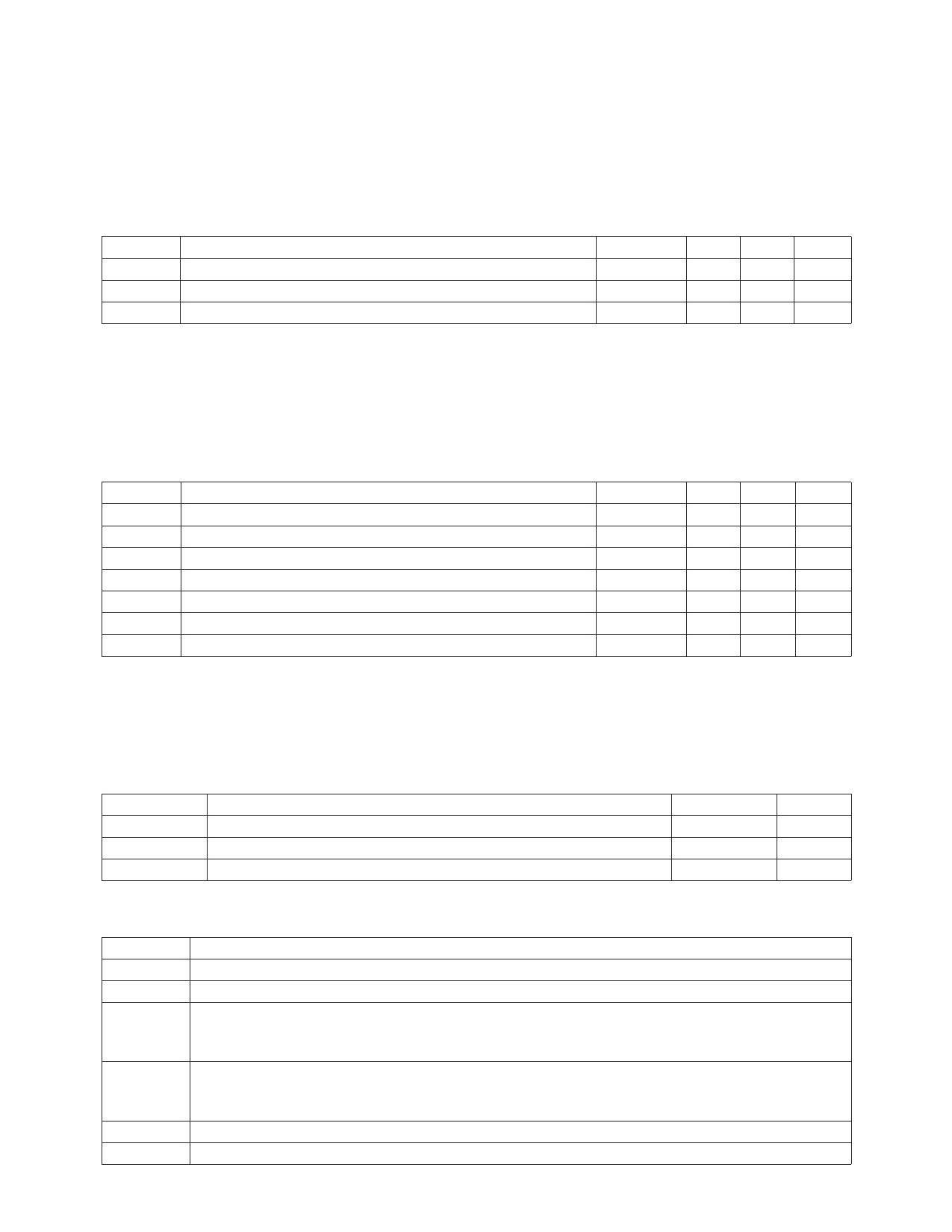
HDMP-1512 (Tx)
Timing Characteristics
TC = 0°C to +85°C, VCC = 4.5 V to 5.5 V, PPSEL = 0, SPDSEL = 1
Symbol
Parameter
ts
Setup Time
th
t_txlat
Hold Time
Transmit Lateny[1]
Units
nsec
nsec
nsec
Min.
Typ.
18
Max.
2
2.3
Note:
1. The Transmitter Latency is defined as the delay time from when a valid data word at TX[00:19] is clocked into the transmitter
(triggered by the rising edge of TBC during the time th) and when the first serial bit is transmitted on pins ± SO (defined by the
leading edge of the first bit transmitted).
HDMP-1514 (Rx)
Timing Characteristics
TC = 0°C to +85°C, VCC = 4.5 V to 5.5 V, PPSEL = 0, SPDSEL = 1
Symbol
Parameter
tflock
BLT
Frequency Lock Rate, Loop Filter Capacitor = 0.01 µF
Bit Lock Time
ts
th
ts’
th’
t_rxlat
Setup Time
Hold Time
Setup Time for Data Rx[10:19] in Ping-Pong Mode
Hold Time for Data Rx[10:19] in Ping-Pong Mode
Receive Latency[1]
Units
kHz/µsec
bit times
nsec
nsec
nsec
nsec
nsec
Min.
2.5
6.0
Typ.
100
6
8
38
Max.
2500
Note:
1. The Receiver Latency is defined as the delay time from receiving the first serial bit of a parallel data word (defined by the rising
edge of the first bit received at pins ± DI), and when that word is first clocked out at RX[00:19] (as defined by the falling edge of
RBC0 or RBC1, following time ts).
HDMP-1512 (Tx), HDMP-1514 (Rx)
Thermal Characteristics, TC = 0°C to +85°C
Symbol
Parameter
PD, Tx
PD, Rx
Θjc
Transmitter Power Dissipation, VCC = +5 V
Receiver Power Dissipation, VCC = +5 V
Thermal Resistance, Junction to Case
Units
Watt
Watt
°C/Watt
Typ.
1.6
2
12
I/O Type Definitions
I/O Type
Definition
I-TTL
O-TTL
O-BLL
I-H50
C
Input TTL. Floats high when left open.
Output TTL.
50 Ω buffer line logic output driver. Should be ac coupled to drive 50 Ω loads. It can also
drive the I-H50 inputs through differential direct coupling. Note: all unused outputs should
be terminated with 50 Ω to VCC.
Input with internal 50 Ω terminations. Input is diode level shifted so that it can swing around
VCC. Can be driven with single-ended or differential, ac coupled configuration. To avoid
permanent damage, these inputs should not be connected to ground.
External circuit node.
S
Power supply or ground.
666
Share Link: 