PI74FCT162540T Просмотр технического описания (PDF) - Pericom Semiconductor
Номер в каталоге
Компоненты Описание
производитель
PI74FCT162540T Datasheet PDF : 6 Pages
| |||
PI74FCT16540/162540/162H540T
123456789012345678901234567890121234567890123456789012345678901212345678901234567890123456789011621-2B34I5T678B90U12F34F56E78R90/1L23I45N67E890D12R12I3V456E78R90S12
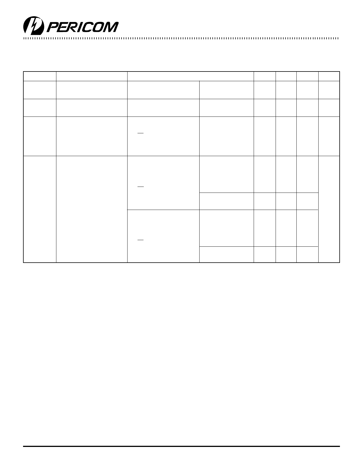
Power Supply Characteristics
Parameters Description
ICC
Quiescent Power
Supply Current
∆ICC
Supply Current per
Input @ TTL HIGH
ICCD
Supply Current per
Input per MHz(4)
IC
Total Power Supply
Current(6)
Test Conditions(1)
VCC = Max.
VIN = GND or VCC
Min. Typ(2) Max. Units
0.1 500 µA
VCC = Max.
VIN = 3.4V(3)
0.5 1.5 mA
VCC = Max.,
Outputs Open
XOE = GND
One Bit Toggling
50% Duty Cycle
VCC = Max.,
Outputs Open
fI = 10 MHZ
50% Duty Cycle
XOE = GND
One Bit Toggling
VCC = Max.,
Outputs Open
fI = 2.5 MHZ
50% Duty Cycle
XOE = GND
16 Bits Toggling
VIN = VCC
VIN = GND
VIN = VCC
VIN = GND
VIN = 3.4V
VIN = GND
VIN = VCC
VIN = GND
VIN = 3.4V
VIN = GND
60 100 µA/
MHz
0.6 1.5(5) mA
0.9 2.3(5)
2.4 4.5(5)
6.4 16.5(5)
Notes:
1. For Max. or Min. conditions, use appropriate value specified under Electrical Characteristics for the applicable device.
2. Typical values are at Vcc = 5.0V, +25°C ambient.
3. Per TTL driven input (VIN = 3.4V); all other inputs at Vcc or GND.
4. This parameter is not directly testable, but is derived for use in Total Power Supply Calculations.
5. Values for these conditions are examples of the Icc formula. These limits are guaranteed but not tested.
6. IC =IQUIESCENT + IINPUTS + IDYNAMIC
IC = ICC + ∆ICC DHNT + ICCD (fCP/2 + fINI)
ICC = Quiescent Current
∆ICC = Power Supply Current for a TTL High Input (VIN = 3.4V)
DH = Duty Cycle for TTL Inputs High
NT = Number of TTL Inputs at DH
ICCD = Dynamic Current Caused by an Input Transition Pair (HLH or LHL)
fCP = Clock Frequency for Register Devices (Zero for Non-Register Devices)
fI = Input Frequency
NI = Number of Inputs at fI
All currents are in milliamps and all frequencies are in megahertz.
5
PS2036A 03/11/96
Share Link: 