ADN4667 Просмотр технического описания (PDF) - Analog Devices
Номер в каталоге
Компоненты Описание
производитель
ADN4667 Datasheet PDF : 16 Pages
| |||
Data Sheet
ADN4667
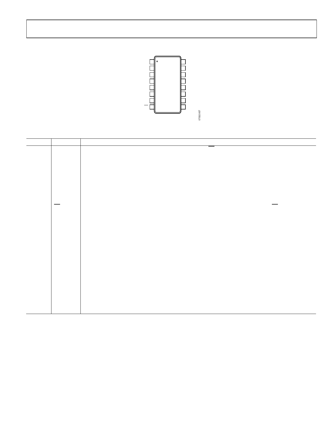
PIN CONFIGURATION AND FUNCTION DESCRIPTIONS
EN 1
DIN1 2
DIN2 3
VCC 4
GND 5
DIN3 6
DIN4 7
EN 8
16 DOUT1–
15 DOUT1+
ADN4667
TOP VIEW
(Not to Scale)
14 DOUT2+
13 DOUT2–
12 DOUT3–
11 DOUT3+
10 DOUT4+
9 DOUT4–
NC = NO CONNECT
Figure 7. Pin Configuration
Table 4. Pin Function Descriptions
Pin No. Mnemonic Description
1
EN
Active High Enable and Power-Down Input (3 V TTL/CMOS). If EN is held low or open circuit, EN enables the
drivers when high and disables the drivers when low.
2
DIN1
Driver Channel 1 Logic Input.
3
DIN2
Driver Channel 2 Logic Input.
4
VCC
Power Supply Input. These parts can be operated from 3.0 V to 3.6 V. The supply should be decoupled with a
10 μF solid tantalum capacitor in parallel with a 0.1 μF capacitor to GND.
5
GND
Ground Reference Point for All Circuitry on the Part.
6
DIN3
Driver Channel 3 Logic Input.
7
DIN4
Driver Channel 4 Logic Input.
8
EN
Active Low Enable and Power-Down Input with Pull-Down (3 V TTL/CMOS). If EN is held high, EN enables the
drivers when low or open circuit and disables the drivers and powers down the device when high.
9
DOUT4−
Channel 4 Inverting Output Current Driver. When DIN4 is high, current flows into DOUT4−. When DIN4 is low, current
flows out of DOUT4−.
10
DOUT4+
Channel 4 Noninverting Output Current Driver. When DIN4 is high, current flows out of DOUT4+. When DIN4 is low,
current flows into DOUT4+.
11
DOUT3+
Channel 3 Noninverting Output Current Driver. When DIN3 is high, current flows out of DOUT3+. When DIN3 is low,
current flows into DOUT3+.
12
DOUT3−
Channel 3 Inverting Output Current Driver. When DIN3 is high, current flows into DOUT3−.When DIN3 is low, current
flows out of DOUT3−.
13
DOUT2−
Channel 2 Inverting Output Current Driver. When DIN2 is high, current flows into DOUT2−. When DIN2 is low, current
flows out of DOUT2−.
14
DOUT2+
Channel 2 Noninverting Output Current Driver. When DIN2 is high, current flows out of DOUT2+. When DIN2 is low,
current flows into DOUT2+.
15
DOUT1+
Channel 1 Noninverting Output Current Driver. When DIN1 is high, current flows out of DOUT1+. When DIN1 is low,
current flows into DOUT1+.
16
DOUT1−
Channel 1 Inverting Output Current Driver. When DIN1 is high, current flows into DOUT1−. When DIN1 is low, current
flows out of DOUT1−.
Rev. B | Page 7 of 16
Share Link: 