AU5517D Просмотр технического описания (PDF) - Philips Electronics
Номер в каталоге
Компоненты Описание
производитель
AU5517D Datasheet PDF : 18 Pages
| |||
Philips Semiconductor
Dual operational transconductance amplifier
Product data
NE5517/NE5517A/
AU5517
V+
11
D4
Q6
Q7
D6
Q10
Q11
Q14
Q12
7,10
Q13
8,9
2,15
D2
–INPUT
4,13
Q4
Q5
D3
+INPUT
3,14
VOUTPUT
5,12
1,16
AMP BIAS
Q2
INPUT
Q1
Q9
Q8
Q15 Q16
D7
R1
D8
D1
D5
V–
6
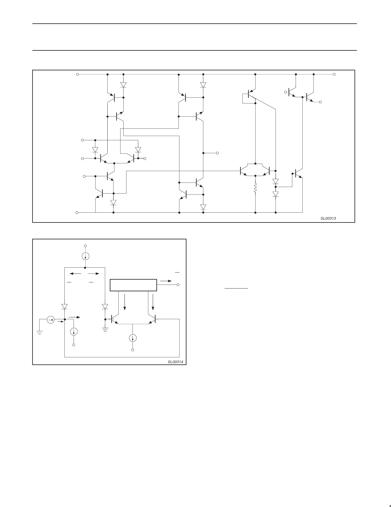
Figure 8. Circuit Diagram of NE5517
Q3
SL00313
+VS
ID
ID
ID
2 * IS 2 ) IS
ǒ ǓIB
I0 + 2 IS ID
I0 + I5 * I4
D3
1/2ID
IS IS
1/2ID
I4
D2
Q4
I5
I5
IB
–VS
Figure 9. Linearizing Diode
SL00314
Stereo Amplifier With Gain Control
Figure 11 shows a stereo amplifier with variable gain via a control
input. Excellent tracking of typical 0.3 dB is easy to achieve. With
the potentiometer, RP, the offset can be adjusted. For AC-coupled
amplifiers, the potentiometer may be replaced with two 510 Ω
resistors.
Modulators
Because the transconductance of an OTA (Operational
Transconductance Amplifier) is directly proportional to IABC, the
amplification of a signal can be controlled easily. The output current
is the product from transconductance×input voltage. The circuit is
effective up to approximately 200 kHz. Modulation of 99% is easy to
achieve.
Voltage-Controlled Resistor (VCR)
Because an OTA is capable of producing an output current
proportional to the input voltage, a voltage variable resistor can be
made. Figure 13 shows how this is done. A voltage presented at the
RX terminals forces a voltage at the input. This voltage is multiplied
by gM and thereby forces a current through the RX terminals:
RX= R ) RA
gM ) RA
where gM is approximately 19.21 µMHOs at room temperature.
Figure 14 shows a Voltage Controlled Resistor using linearizing
diodes. This improves the noise performance of the resistor.
Voltage-Controlled Filters
Figure 15 shows a Voltage Controlled Low-Pass Filter. The circuit is
a unity gain buffer until XC/gM is equal to R/RA. Then, the frequency
response rolls off at a 6dB per octave with the –3 dB point being
defined by the given equations. Operating in the same manner, a
Voltage Controlled High-Pass Filter is shown in Figure 16. Higher
order filters can be made using additional amplifiers as shown in
Figures 17 and 18.
Voltage-Controlled Oscillators
Figure 19 shows a voltage-controlled triangle-square wave
generator. With the indicated values a range from 2 Hz to 200 kHz is
possible by varying IABC from 1 mA to 10 µA.
The output amplitude is determined by IOUT × ROUT.
Please notice the differential input voltage is not allowed to be above
5 V.
With a slight modification of this circuit you can get the sawtooth
pulse generator, as shown in Figure 20.
2002 Dec 06
10
Share Link: 