ADSP-21160NKB-95 Просмотр технического описания (PDF) - Analog Devices
Номер в каталоге
Компоненты Описание
производитель
ADSP-21160NKB-95 Datasheet PDF : 53 Pages
| |||
PRELIMINARY TECHNICAL DATA
April 2002
For current information contact Analog Devices at 800/262-5643
ADSP-21160N
Also, the clearance (length, width, and height) around the
header must be considered. Leave a clearance of at least
0.15" and 0.10" around the length and width of the header,
and reserve a height clearance to attach and detach the pod
connector.
GND
KEY (NO PIN)
BTMS
BTCK
BTRST
BTDI
GND
1
3
5
7
9
9
11
13
2
EMU
4
GND
6
TMS
8
TCK
10
TRST
12
TDI
14
TDO
TOP VIEW
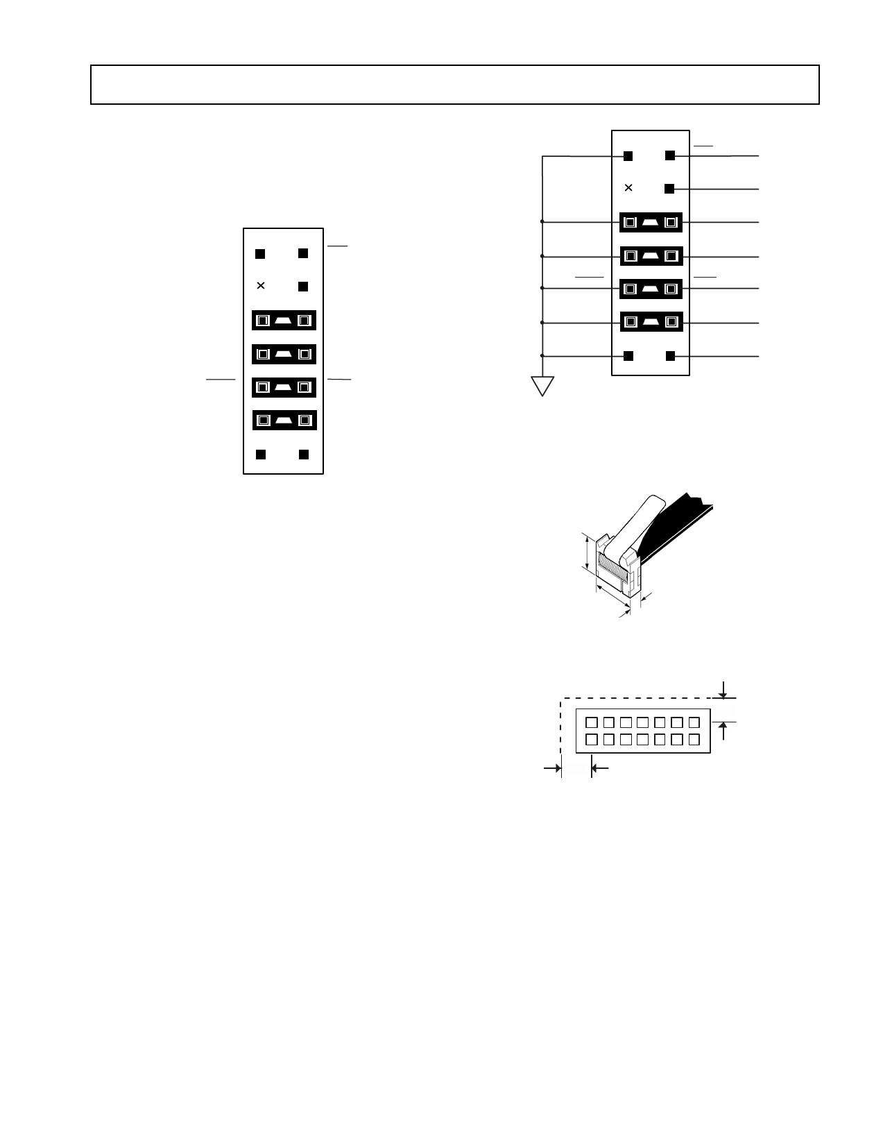
Figure 6. JTAG Target Board Connector for JTAG
Equipped Analog Devices DSP (Jumpers in
Place)
1
GND
3
KEY (NO PIN)
5
BTMS
7
BTCK
BTRST
BTDI
9
9
11
13
GND
2
EMU
4
GND
6
TMS
8
TCK
10
TRST
12
TDI
14
TDO
TOP VIEW
Figure 7. JTAG Target Board Connector with No Local
Boundary Scan
0.64"
As can be seen in Figure 6, there are two sets of signals on
the header. There are the standard JTAG signals TMS,
TCK, TDI, TDO, TRST, and EMU used for emulation
purposes (via an emulator). There are also secondary JTAG
signals BTMS, BTCK, BTDI, and BTRST that are option-
ally used for board-level (boundary scan) testing.
When the emulator is not connected to this header, place
jumpers across BTMS, BTCK, BTRST, and BTDI as
shown in Figure 7. This holds the JTAG signals in the
correct state to allow the DSP to run free. Remove all the
jumpers when connecting the emulator to the JTAG header.
JTAG Emulator Pod Connector
Figure 8 details the dimensions of the JTAG pod connector
at the 14-pin target end. Figure 9 displays the keep-out area
for a target board header. The keep-out area allows the pod
connector to properly seat onto the target board header.
This board area should contain no components (chips,
resistors, capacitors, etc.). The dimensions are referenced
to the center of the 0.25" square post pin.
Design-for-Emulation Circuit Information
For details on target board design issues including: single
processor connections, multiprocessor scan chains, signal
buffering, signal termination, and emulator pod logic, see
the EE-68: Analog Devices JTAG Emulation Technical
Reference on the Analog Devices website—use site search on
0.88"
0.24"
Figure 8. JTAG Pod Connector Dimensions
0 .10 "
0.1 5"
Figure 9. JTAG Pod Connector Keep-Out Area
“EE-68” (www.analog.com). This document is updated
regularly to keep pace with improvements to emulator
support.
Additional Information
This data sheet provides a general overview of the
ADSP-21160N architecture and functionality. For detailed
information on the ADSP-2116x Family core architecture
and instruction set, refer to the ADSP-2116x SHARC DSP
Hardware Reference.
REV. PrB This information applies to a product under development. Its characteristics and specifications are subject to change without notice. Analog
8
Devices assumes no obligation regarding future manufacturing unless otherwise agreed to in writing.
Share Link: 