XE1203 Просмотр технического описания (PDF) - Unspecified
Номер в каталоге
Компоненты Описание
производитель
XE1203 Datasheet PDF : 37 Pages
| |||
RTParam_FEI
Data Sheet
XE1203
en
fei_out
saout_fei
TS_FEI
xxx
first evaluation
val1
val0
2/BR
val2
val3
val4 0
Dataout_MSB_fei&
xxx
Dataout_LSB_fei
val1
val3
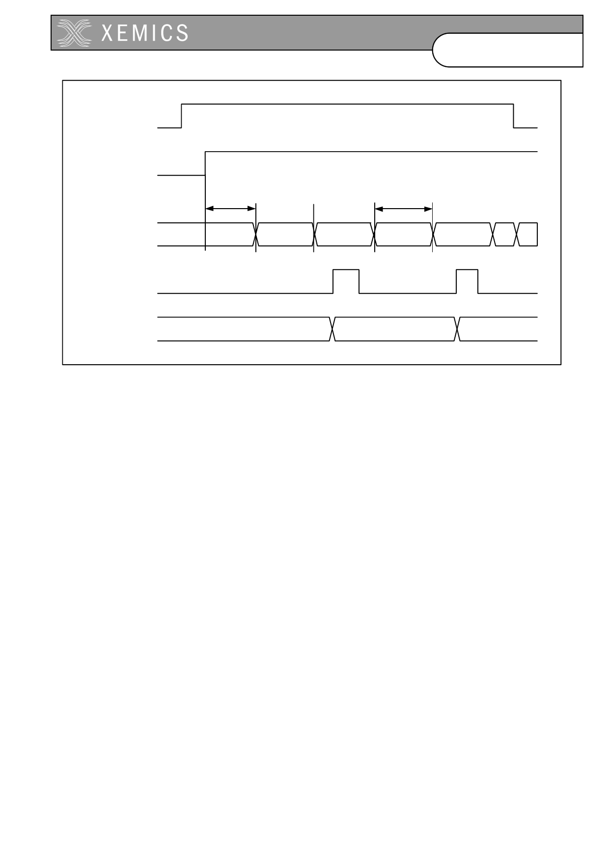
Figure 8 Time diagram of an FEI measurement.
To guarantee proper behaviour of the FEI, the sum of the frequency offset and the signal bandwidth (single sided)
should be lower than the baseband filter bandwidth (single sided). That is:
Foffset + SignalBW < Baseband_filterBW.
Where foffset is the difference between the carrier frequency and the LO frequency, SignalBW is the signal
bandwidth (single side) equal to the sum of the bit rate divided by 2 and the frequency deviation ( BR/2 + DF), and
Baseband_filterBW is the channel filter bandwidth defined by RTParam_BW parameters.
The frequency error can be calculated by the following formula:
The frequency error = (BR/8)*int(Dataout_FEI(11:0)),
Where Dataout_FEI(11:0) = Dataout_MSB_fei(3:0) & Dataout_LSB_fei(7:0) and int(x) is the integer value of the
signed binary representation of x.
Saout_fei is internally generated during a read sequence of “Dataout_LSB_fei ‘’ register in the same way as
saout_rssi. The maximum frequency of SCK during the read operation of the RSSI value is 100 KHz.
When using the Konnex standard, the bit ADParam_enable_konnex (address “01111”) has to be set to ‘1’.
4.1.11 Transmitter
The transmit data should be applied to DATA or DATAIN pins depending on the ADParam_disable_data_bidir
register setting. If it is set to high (“1”) the DATAIN pin is used otherwise bidirectional pin DATA is used for transmit
data. The modulation of LO with the data applied can be performed with pre-filtering or without. The pre-filtering
can be selected by setting RTParam_Filter register to high (“1”). So, the modulation of the LO frequency by the bit
stream can be made in two ways:
• The input bit stream is directly applied to the frequency synthesizer without any pre-filtering,
• The input bit stream is pre-filtered before being applied to the frequency synthesizer; with this filtering,
each edge of the bit stream is linearly smoothed with a staircase transition.
The two possible ways of modulation are shown in figure 4-9, where “datain” is the input bit stream.
15
D0308-214
Share Link: 