WM8772(2005) Просмотр технического описания (PDF) - Wolfson Microelectronics plc
Номер в каталоге
Компоненты Описание
производитель
WM8772 Datasheet PDF : 73 Pages
| |||
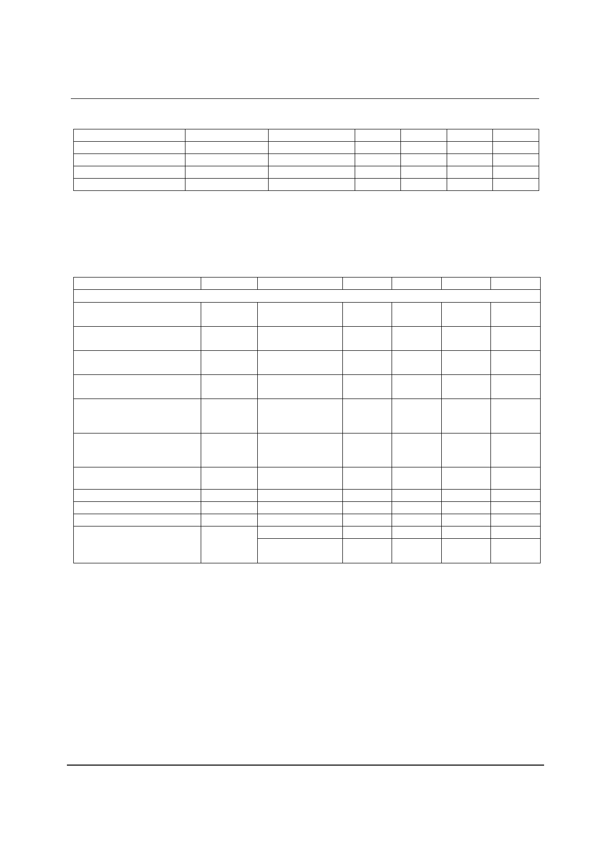
WM8772
Production Data
RECOMMENDED OPERATING CONDITIONS
PARAMETER
SYMBOL
TEST CONDITIONS
MIN
Digital supply range
DVDD
2.7
Analogue supply range
AVDD, VREFP
2.7
Ground
AGND, VREFN, DGND
Difference DGND to AGND
-0.3
Note: Digital supply DVDD must never be more than 0.3V greater than AVDD.
TYP
0
0
MAX
3.6
5.5
+0.3
UNIT
V
V
V
V
ELECTRICAL CHARACTERISTICS
Test Conditions
AVDD, VREFP = 5V, DVDD = 3.3V, AGND, VREFN = 0V, DGND = 0V, TA = +25oC, fs = 48kHz, MCLK = 256fs, 32-pin TQFP
version unless otherwise stated. ADC/DAC in Slave Mode unless otherwise stated.
PARAMETER
SYMBOL TEST CONDITIONS
MIN
DAC Performance (Load = 10kΩ, 50pF)
TYP
MAX
UNIT
0dBFs Full scale output voltage
1.0 x
Vrms
VREFP/5
SNR (Note 1,2,4)
A-weighted,
95
103
dB
@ fs = 48kHz
SNR (Note 1,2,4)
A-weighted
102
dB
@ fs = 96kHz
SNR (Note 1,2,4)
A-weighted
101
dB
@ fs = 192kHz
SNR (Note 1,2,4)
A-weighted
99
dB
@ fs = 48kHz, AVDD =
3.3V
SNR (Note 1,2,4)
A-weighted
99
dB
@ fs = 96kHz, AVDD =
3.3V
Dynamic Range (Note 2,4)
DNR
A-weighted, -60dB full
90
103
dB
scale input
Total Harmonic Distortion (THD)
1kHz, 0dB.Fs
-90
-80
dB
Mute Attenuation
1kHz Input, 0dB gain
100
dB
DAC channel separation
100
dB
Power Supply Rejection Ratio
PSRR
1kHz 100mVp-p
50
dB
20Hz to 20kHz
45
dB
100mVp-p
w
PD Rev 4.2 October 2005
10
Share Link: 