W77E516 Просмотр технического описания (PDF) - Winbond
Номер в каталоге
Компоненты Описание
производитель
W77E516 Datasheet PDF : 85 Pages
| |||

Preliminary W77E516
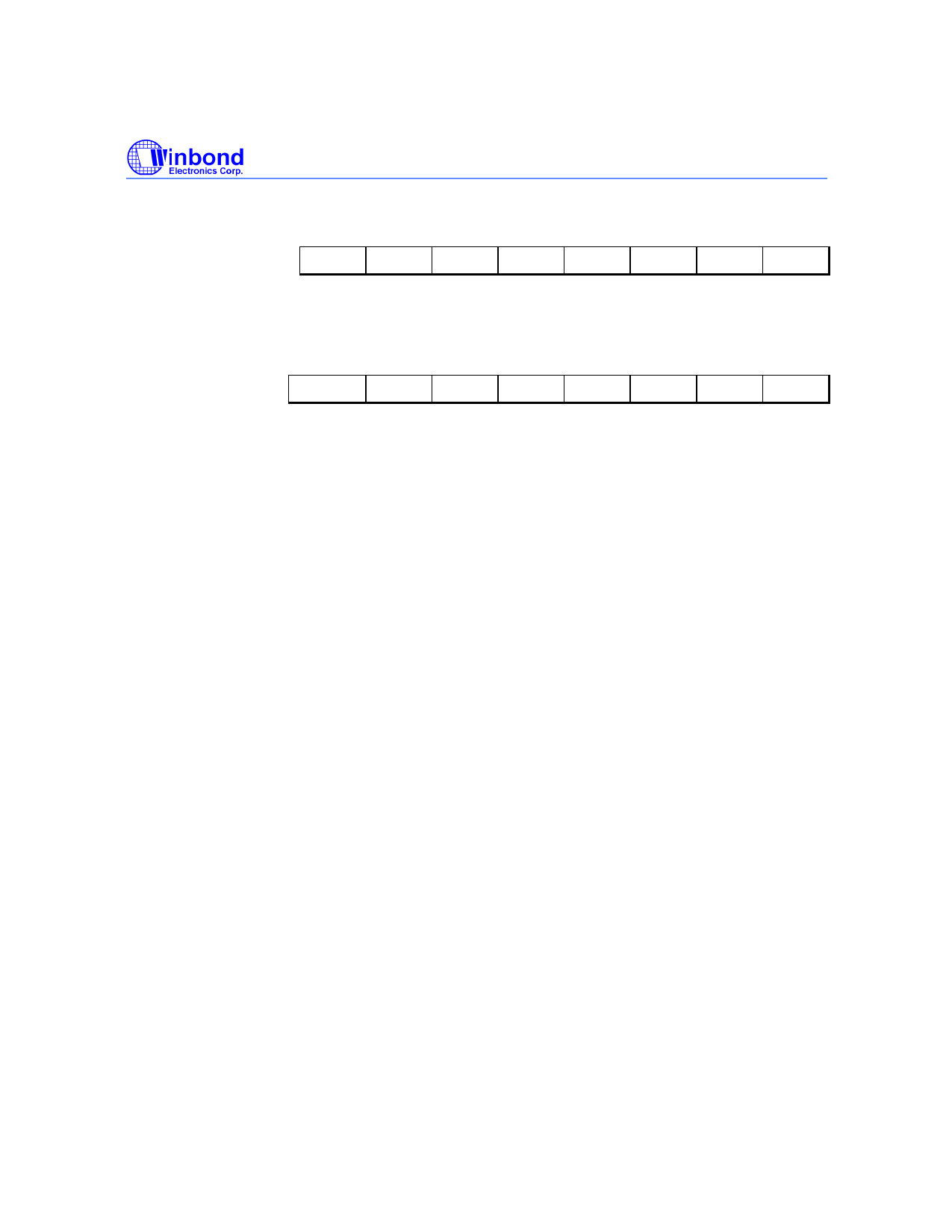
P4.1 Base Address High Byte Register
Bit:
7
6
5
4
3
2
1
0
A15 A14 A13 A12 A11 A10
A9
A8
Mnemonic: P41AH
Address: 97h
Serial Port Control
Bit:
7
6
5
4
3
2
1
0
SM0/FE SM1 SM2 REN TB8 RB8
TI
RI
Mnemonic: SCON
Address: 98h
SM0/FE: Serial port 0, Mode 0 bit or Framing Error Flag: The SMOD0 bit in PCON SFR determines
whether this bit acts as SM0 or as FE. The operation of SM0 is described below. When
used as FE, this bit will be set to indicate an invalid stop bit. This bit must be manually
cleared in software to clear the FE condition.
SM1: Serial port Mode bit 1:
SM0
0
0
1
1
SM1
0
1
0
1
Mode
0
1
2
3
Description
Synchronous
Asynchronous
Asynchronous
Asynchronous
Length
8
10
11
11
Baud rate
4/12 Tclk
Variable
64/32 Tclk
Variable
SM2: Multiple processors communication. Setting this bit to 1 enables the multiprocessor
communication feature in mode 2 and 3. In mode 2 or 3, if SM2 is set to 1, then RI will not be
activated if the received 9th data bit (RB8) is 0. In mode 1, if SM2 = 1, then RI will not be
activated if a valid stop bit was not received. In mode 0, the SM2 bit controls the serial port
clock. If set to 0, then the serial port runs at a divide by 12 clock of the oscillator. This gives
compatibility with the standard 8052. When set to 1, the serial clock become divide by 4 of the
oscillator clock. This results in faster synchronous serial communication.
REN: Receive enable: When set to 1 serial reception is enabled, otherwise reception is disabled.
TB8: This is the 9th bit to be transmitted in modes 2 and 3. This bit is set and cleared by software
as desired.
RB8: In modes 2 and 3 this is the received 9th data bit. In mode 1, if SM2 = 0, RB8 is the stop bit
that was received. In mode 0 it has no function.
TI: Transmit interrupt flag: This flag is set by hardware at the end of the 8th bit time in mode 0, or
at the beginning of the stop bit in all other modes during serial transmission. This bit must be
cleared by software.
RI: Receive interrupt flag: This flag is set by hardware at the end of the 8th bit time in mode 0, or
halfway through the stop bits time in the other modes during serial reception. However the
restrictions of SM2 apply to this bit. This bit can be cleared only by software.
- 19 -
Publication Release Date: August 16, 2002
Revision A1