VDP3108 Просмотр технического описания (PDF) - Micronas
Номер в каталоге
Компоненты Описание
производитель
VDP3108 Datasheet PDF : 61 Pages
| |||
ADVANCE INFORMATION
VDP 3108
2. Functional Description
2.1.3. Automatic Gain Control
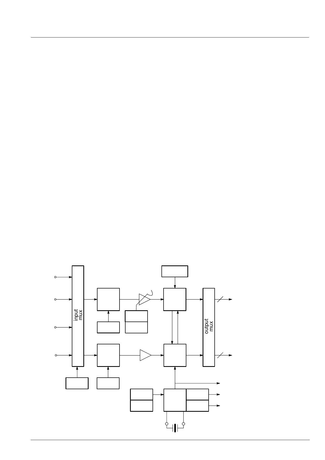
2.1. Analog Front End
This block provides the analog interfaces to all video in-
puts and mainly carries out analog-to digital conversion
for the following digital video processing. A block dia-
gram is given in figure 2–1.
Most of the functional blocks in the front end are digitally
controlled (clamping, AGC and clock-DCO). The control
loops are closed by the Fast Processor (‘FP’) embedded
in the decoder.
2.1.1. Input Selector
Up to four analog inputs can be connected. Three inputs
are for input of composite video or S–VHS luma signal.
These inputs are clamped to the sync back porch and
are amplified by a variable gain amplifier. One input is
for connection of S–VHS carrier–chrominance signal.
This input is internally biased and has a fixed gain ampli-
fier.
2.1.2. Clamping
A digitally working automatic gain control adjusts the
magnitude of the selected baseband by +6/–4.5 dB in 64
logarithmic steps to the optimal range of the ADC .
The gain of the video input stage including the ADC is
213 steps/V for all three standards (PAL/NTSC/SECAM/
Y/C), with the AGC set to 0 dB.
2.1.4. Analog-to-Digital Converters
Two ADCs are provided to digitize the input signals.
Each converter runs with 20.25 MHz and has 8 bit reso-
lution. An integrated bandgap circuit generates the re-
quired reference voltages for the converters.
The two ADCs are of a 2-stage subranging type.
2.1.5. ADC Range
The ADC input range for the various input signals and
the digital representation is given in table 2–1 and figure
2–2.
The composite video input signals are AC coupled to the
IC. The clamping voltage is stored on the coupling ca-
pacitors and is generated by digitally controlled current
sources. The clamping level is the back porch of the vid-
eo signal. S-VHS chroma is also AC coupled. The input
pin is internally biased to the center of the ADC input
range.
2.1.6. Digitally Controlled Clock Oscillator
The clock generation is also a part of the analog front
end. The crystal oscillator is controlled digitally by the
control processor; the clock frequency can be adjusted
within ±150 ppm.
VIN3
CVBS/Y
reference
generation
AGC
+6/–4.5dB
VIN2
CVBS/Y
clamp
ADC
8
digital
CVBS
or Y
CVBS/ VIN1
Y/C
C
CIN
level
DAC
gain
bias/
clamp
ADC
to
color
decod-
er
8
digital
chro-
ma
select
level
Fig. 2–1: Analog front end
DAC
freq.
DVC
O
± 150
ppm
frequ.
doubler
frequ.
divider
20.25
MHz
sys-
tem
clocks
MICRONAS INTERMETALL
5
Share Link: 