VCC6-107 Просмотр технического описания (PDF) - Vectron International
Номер в каталоге
Компоненты Описание
производитель
VCC6-107 Datasheet PDF : 6 Pages
| |||
VCC6-107 Crystal Oscillator
Performance Characteristics
Table 1. Electrical Performance
Parameter
Frequency
Supply Voltage 1
Supply Current
Output Logic Levels
Output Logic High2
Output Logic Low2
Transition Times
Rise Time2
Fall Time2
Output Load
Symmetry or Duty Cycle3
Operating temperature
Stability 4
RMS Jitter, 12kHz to 20 MHz
Period RMS Jitter
Cycle to Cycle RMS Jitter
Output Enabled5
Output Disabled5
Output Enable/Disable time
Enable/Disable Leakage Current
Package Size
Symbol
fO
VDD
IDD
Min
40
3.135
Typical
3.3
Maximum
200
3.465
98
Units
MHz
V
mA
VOH
VDD-1.025
VOL
VDD-1.810
VDD-0.880
V
VDD-1.620
V
tR
tF
SYM
IE/D
600
600
50 ohms to VDD-2V
45
50
55
-10/70
+/-20
0.3
0.7
2.7
4.8
0.7*VDD
0.3*VDD
400
±200
5.0 x 7.0 x 1.5
ps
ps
%
°C
ppm
ps
ps
ps
V
V
ns
uA
mm
1. A 0.01uF and a 0.1uF capacitor should be located as close to the supply as possible (to ground) is recommended.
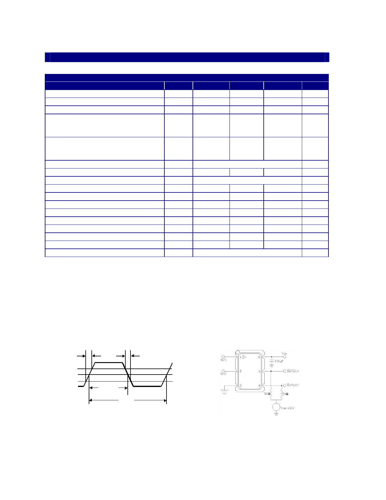
2. Figure 1 defines these parameters. Figure 2 illustrates the operating conditions under which
these parameters are tested and specified.
3. Symmetry is defined as Vs, On Time/Period.
4. Includes calibration tolerance, operating temperature, supply voltage variations, aging (10 years @ 40 degreesC) and shock
and vibration (not under operation).
5. Output will be enabled if enable/disable is left open.
6. Jitter is measured using a LeCroy8600 sampling 50,000 cycles.
80 %
Vs
20 %
tR
tF
On Time
Period
Figure 1. Output Waveform
Figure 2. Typical Output Test Conditions (25±5°C)
Vectron International 267 Lowell Rd, Hudson NH 03051 Tel: 1-88-VECTRON-1 e-mail: vectron@vectron.com
Share Link: 