US431AL Просмотр технического описания (PDF) - Unisem
Номер в каталоге
Компоненты Описание
производитель
US431AL Datasheet PDF : 6 Pages
| |||
US431L/431AL
ABSOLUTE MAXIMUM RATINGS
Input Voltage (Vin) ............................................................. 7V
Continuous Cathode Current Range ......................................... -20 mA to +20 mA
Reference Current Range ...................................................... -0.05 mA to 3 mA
Storage Temperature Range ................................ -65°C TO 150°C
Operating Junction Temperature Range ...................... 0°C TO 150°C
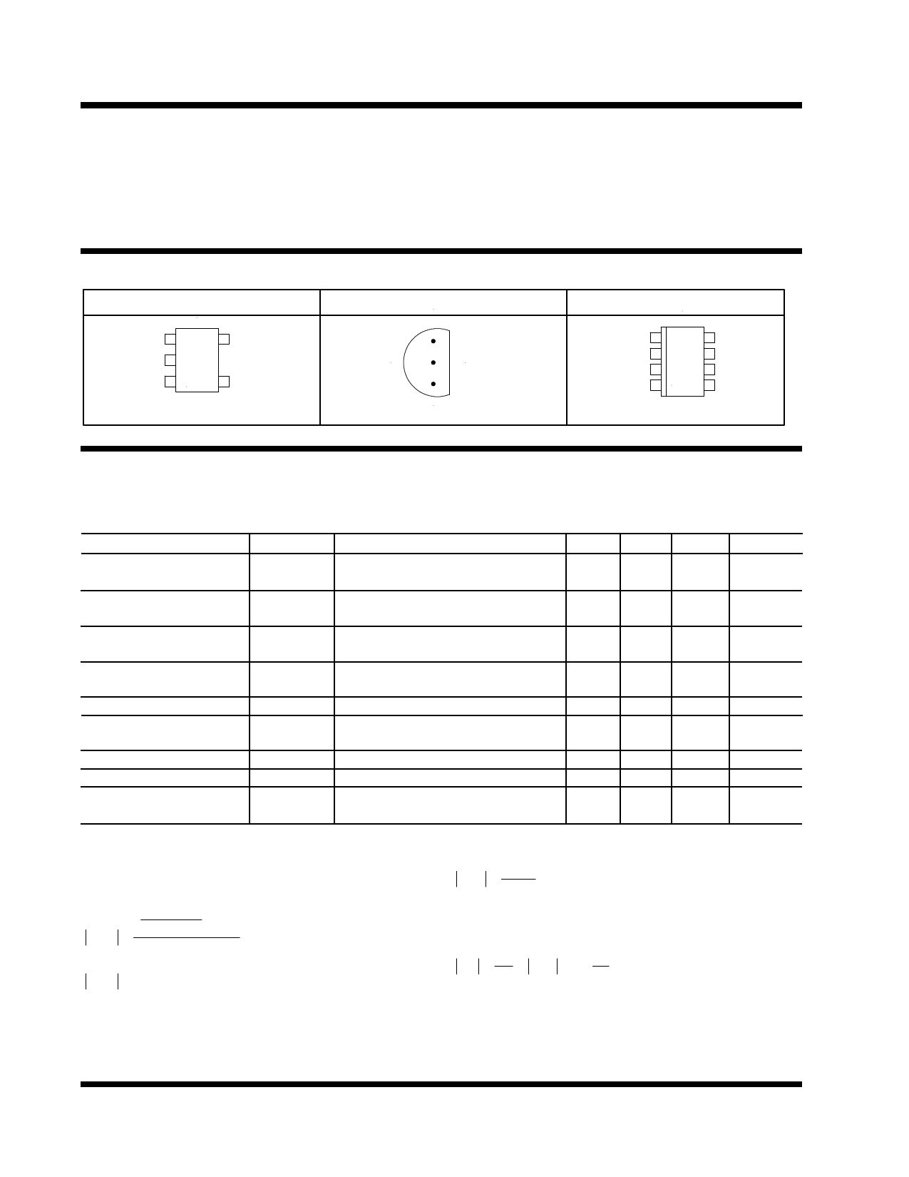
PACKAGE INFORMATION
5 PIN SOT 23 (L)
TOP VIEW
NC 1
5 Anode
NC 2
Cathode 3
4 Ref
θJA = 450°C/W
3 PIN PLASTIC TO-92 (Z)
BOTTOM VIEW
1 Ref
2 Anode
3 Cathode
θJA = 162°C/W
8 PIN PLASTIC SOIC (S)
TOP VIEW
Cathode 1
8 Ref
NC 2
7 NC
Anode 3
6 Anode
NC 4
5 NC
θJA=160°C/W
ELECTRICAL SPECIFICATIONS
Unless otherwise specified ,these specifications apply over Ta=0 to 70 °C, CO =1uF. Typical values refer to
Ta=25 °C.Low duty cycle pulse testing are used which keeps junction and case temperatures equal to the
ambient temperature.
PARAMETER
SYM
Reference Voltage
Vref
US431L
Reference Voltage
Vref
US431AL
Vref deviation over full Vref(dev)
temperature range
Ratio of Vref change to dVref/dVKA
Cathode voltage change
Reference pin current
Iref deviation over full Iref(dev)
temperature range
Minimum cathode current IK(min)
Off state cathode current Ioff
Dynamic impedance
Zka0
TEST CONDITION
IK=10mA,VKA=Vref,Ta=25°C
IK=10mA,VKA=Vref
IK=10mA,VKA=Vref,Ta=25°C
IK=10mA,VKA=Vref
VKA=Vref, IK=10mA
Note 1
IK=10mA , dVKA=Vref to 6 V
IK=10mA , R1=10kΩ , R2=open
IK=10mA , R1=10kΩ , R2=open
Note 1
VKA=Vref
VKA=6V , Vref=0V
VKA=Vref, f<1 kHz,
IK=0.1 to 15 mA , Note 2
MIN
1.228
1.221
1.234
1.228
TYP MAX
1.240 1.252
1.240 1.259
1.240 1.246
1.240 1.252
4
12
UNITS
V
V
mV
-1.5 -2.7 mV/V
0.15 0.5
uA
0.05 0.3
uA
55 80
uA
0.001 0.1
uA
0.25 0.4
Ω
Note 1 : The deviation parameters, Vref(dev) and Iref(dev) are
defined as the differences between the maximum and the minimum
values obtained over the rated temperature range. The average full
range temperature coeficient of the reference input voltage is de-
fined as :
αVref
=
Vref(dev)
Vref(25° C)
×
106
∆TA
Where:
αVref unit is ppm/° C
Note 2 :
Thedynamic impedance when VKA = Vref is defined as :
Zka0 = ∆VKA
∆IK
When the device is operating with two external
resistors (see Figure 2), the total dynamic impedance
of the circuit is given by:
Zka
=
∆V
∆I
=
Zka0
×
1 +
R1
R2
∆TA is the rated operating free air temperature
of the device.
αVref can be positive or negative depending on whether
minimum Vref or maximum Vref, respectively occurs at the
lower temperature.
2-2
Rev. 1.2
5/11/98
Share Link: 