UPD75236GJ Просмотр технического описания (PDF) - NEC => Renesas Technology
Номер в каталоге
Компоненты Описание
производитель
UPD75236GJ Datasheet PDF : 190 Pages
| |||
µPD75236
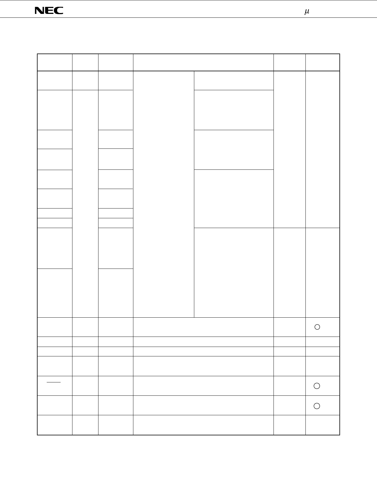
1.2 NON-PORT PINS (1/2)
Pin Name
T0 to T9
T10/S15 to
T13/S12
T14/S11
T15/S10
S0 to S3
S4 to S7
S8
S9
S16 to S19
S20 to S23
TI0
PTO0
PCL
BUZ
Dual-
I/O
Function Pin
Function
Input / Output
After Reset Circuit Type *
Digit output high-voltage high-
—
current output pins.
Output
PH3/P153 to
PH0/P150
P143
P142
P120 to
P123
P130 to
P133
P140
FIP controller/driver
output pins.
Pull-down resistor can
be incorporated in bit
units (mask option).
Digit/segment output dual-func-
tion high-voltage high-current
output pins. Extra pins can be
used as PORTH. These pins can
be used as PORT15 in the static VLOAD level
mode.
(when a
pull-down
Digit/segment output dual-func- resistor to
tion high-voltage high-current
output pins. These pins can be
used as POTR14 in the static
mode.
VLOAD is
incorpo-
rated) or
high
impedance.
Segment high-voltage output
pins.
These pins can be used as
PORT12 to PORT14 in the static
mode.
P141
P100 to P103
P110 to P113
Segment high-voltage output
pins.
These pins can be used as
PORT10 and PORT11 in the
static mode.
VLOAD level
(when a
pull-down
resistor to
VLOAD is
incorpo-
rated), VSS
level (when
a pull-down
resistor to
VSS is
incorpo-
rated) or
high
impedance
I–C
I–F
External event pulse input pin to timer/event counter #0
Input
P13
and event counter #1.
—
B –C
Output
P20
Timer/event counter output pin
Output
P22
Clock output pin
Input
Input
Output
P23
Fixed frequency output pin (for buzzer or system clock
trimming)
Input
E–B
E–B
E–B
SCK0
Input/
P01
output
Serial clock input/output pin
Input/
Serial data output pin
SO0/SB0
P02
output
Serial bus input/output pin.
Input
Input
F –A
F –B
Input/
Serial data input pin
SI0/SB1
output
P03
Serial bus input/output pin.
Input
M–C
* Schmitt trigger inputs are circled.
9
Share Link: 