UMA1005 Просмотр технического описания (PDF) - Philips Electronics
Номер в каталоге
Компоненты Описание
производитель
UMA1005 Datasheet PDF : 24 Pages
| |||
Philips Semiconductors
Dual low-power frequency synthesizer
Preliminary specification
UMA1005T
stage, which is a 9-bit programmable divider with standard
input frequency (30 MHz). The division ratio can be
expressed as:
If PA = 0; N = 4 × NA.
If PA = 1; N = NA; with NA = 4 to 511.
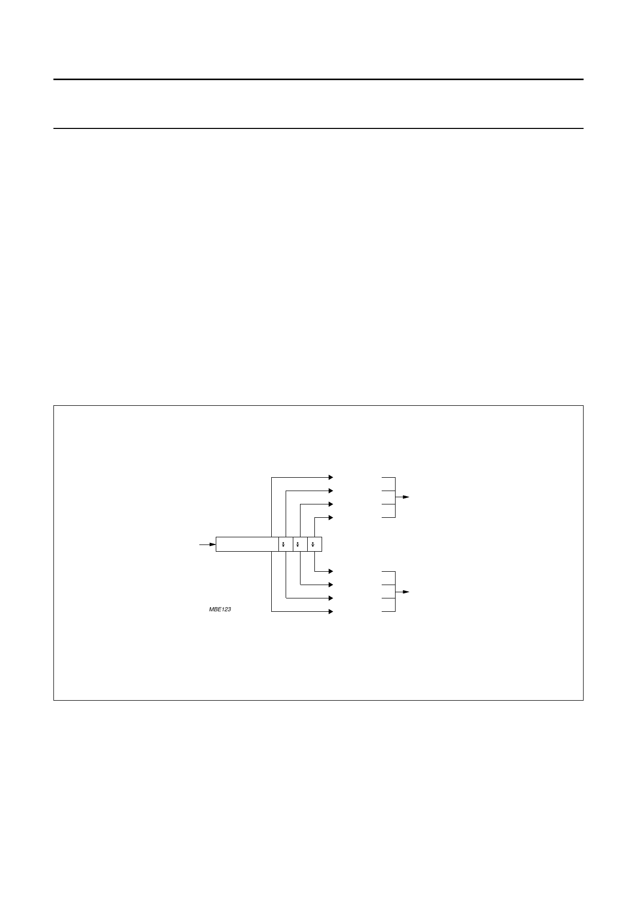
Reference variable divider (Fig.5)
The input signal on INR is amplified to a logic level by a
single ended input buffer, which accepts LOW level AC
coupled input signals. This input stage is enabled by the
OR function of the serial input bits EA and EM. Disabling
means that all currents in the input stage are switched off.
The reference divider consists of a programmable divider
by NR (NR = 4 to 511) followed by a 3-bit binary counter.
The 2-bit SM determines which of the 4 output pulses is
selected as main phase detector input. The 2-bit SA
determines the selection of the auxiliary phase detector
signal. To obtain the best time spacing for the main and
auxiliary reference signals, the opposite output will be
used for the auxiliary phase detector, reducing the
possibility of unwanted interactions. For this reason the
programmable divider produces a symmetric output pulse
for even ratios and a 1 input cycle asymmetric pulse for
odd ratios.
Main variable divider
The input signals on INM1 and INM2 are amplified to a
logic level by a balanced input comparator giving a
common mode rejection. This input stage is enabled when
serial control bit EM = 1. Disabling means that all currents
in the comparator are switched off. The main divider is
built-up by a 12-bit counter plus a sign bit. Depending on
the serial input values of NM1, NM2, NM3, NM4 and the
prescaler select PR, the counter will select a prescaler
ratio during a number of input cycles in accordance with
the information in Table 2.
book, full pagewidth
reference
input
divide by NR
MBE123
MAIN SELECT
SM = ‘00’
SM = ‘01’
SM = ‘10’
SM = ‘11’
2 22
AUXILIARY SELECT
SA = ‘11’
SA = ‘10’
SA = ‘01’
SA = ‘00’
main
phase
detector
auxiliary
phase
detector
Fig.5 Reference variable divider.
November 1994
8
Share Link: 