UEI25-033-D48 Просмотр технического описания (PDF) - Murata Manufacturing
Номер в каталоге
Компоненты Описание
производитель
UEI25-033-D48 Datasheet PDF : 23 Pages
| |||
UEI25 Series
Single Output Isolated 25-Watt DC/DC Converters
PERFORMANCE SPECIFICATIONS SUMMARY AND ORDERING GUIDE ➀ ➂
Output
Input
Root Models ➀
R/N (mVp-p) Regulation (Max.)
IIN, IIN,
IOUT Total
VIN
min. full
VOUT (A, Power
Nom. Range load load
(V) max) (W) Typ. ➁ Max. Line Load (V) (V) (mA) (A)
Efficiency
Min. Typ.
Package, C75
Case (inches) Case (mm)
UEI25-033-D48 ➃
3.3 7.5 25 50 80 ±0.1% ±0.2% 48 36-75 75 0.58 87.0% 89.5% 0.96x1.1x0.32 24.4x27.9x8.1
UEI25-050-D48
5 5 25 50 80 ±0.1% ±0.2% 48 36-75 30 0.57 89.0% 91% 0.96x1.1x0.32 24.4x27.9x8.1
UEI25-120-D48
12 2.1 25.2 95 120 ±0.1% ±0.1% 48 36-75 20 0.6 86.0% 87.5% 0.96x1.1x0.32 24.4x27.9x8.1
Pinout
P85
P85
P85
Notes:
➀ Please refer to the part number structure for additional options and complete order-
ing part numbers.
➁ Ripple and Noise is shown at 20 MHz bandwidth.
➂ All specifications are at nominal line voltage and full load, +25 °C. unless otherwise
noted. See detailed specifications for full conditions.
Output capacitors are 1 μF ceramic in parallel with 10 μF electrolytic. The input cap
is 4.7 μF ceramic, low ESR.
I/O caps are necessary for our test equipment and may not be needed for your ap-
plication.
➃ Minimum load is 10% for rated specifications.
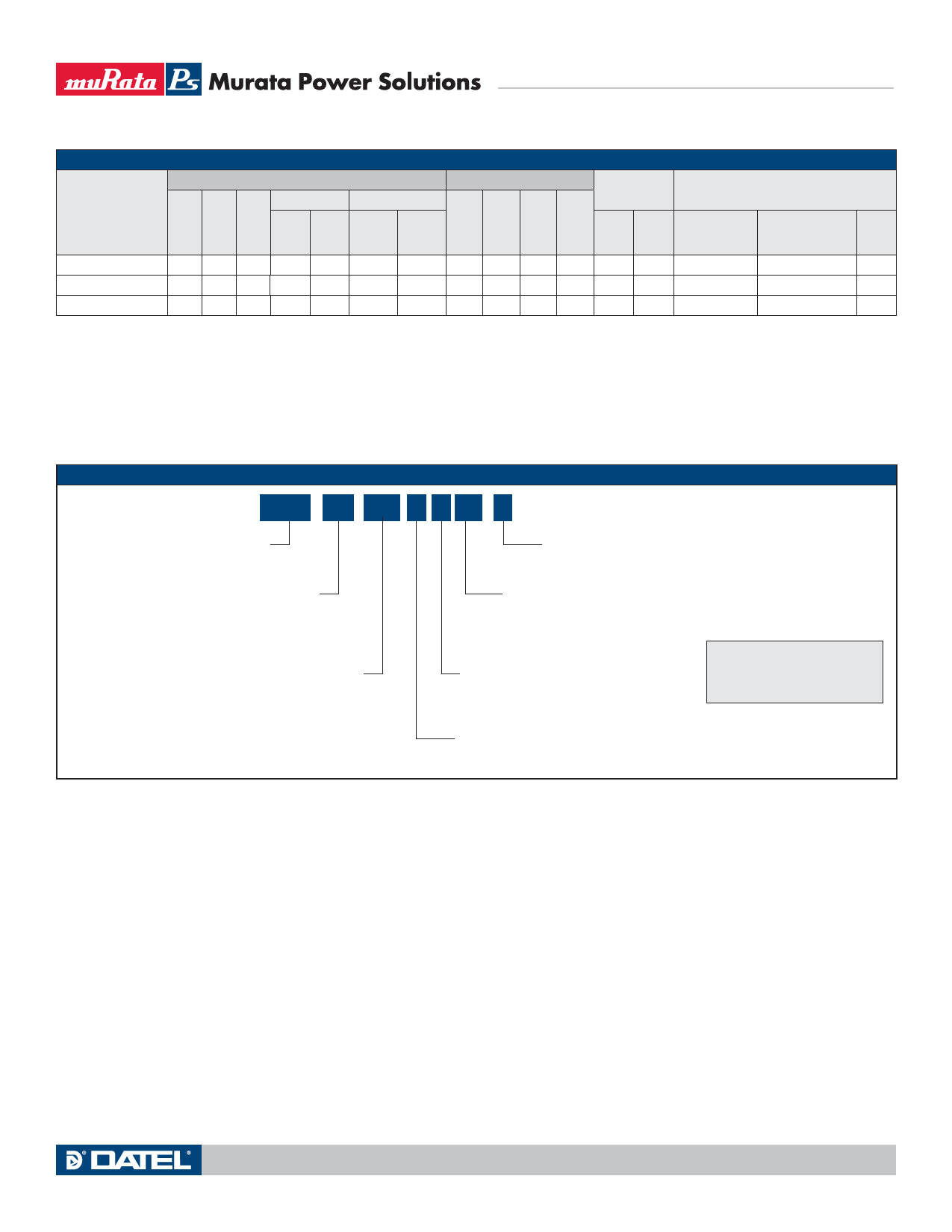
PART NUMBER STRUCTURE
UEI25 - 033 - D48 P M Lx - C
Unipolar Output Isolated
25-Watt Series
RoHS-6 Hazardous Substance Compliance
(Does not claim EU RoHS exemption 7b, lead in solder)
Nominal Output Voltage
in Tenths of a Volt
Input Voltage Range
D48 = 36-75 Vdc
Pin Length Option (through-hole only)
Blank = Std. pin length 0.25˝ (6.3mm)
L1 = 0.110˝ (2.79mm)*
L2 = 0.145˝ (3.68mm)*
Surface Mount Option
Blank = Through-hole mount
M = Surface mount (MSL rating 2)
Note:
Some model number combinations
may not be available.
Contact Murata Power Solutions.
On/Off Control Polarity:
P = Positive
N = Negative
*Alternate pin lengths may
require quantity order.
www.murata-ps.com
MDC_UEI25W.B03 Page 2 of 23
Share Link: 