MAX4370 Просмотр технического описания (PDF) - Maxim Integrated
Номер в каталоге
Компоненты Описание
производитель
MAX4370
Maxim Integrated

MAX4370 Datasheet PDF : 16 Pages
| |||
Current-Regulating Hot-Swap Controller with
DualSpeed/BiLevel Fault Protection
Detailed Description
The MAX4370 is a circuit-breaker IC designed for hot-
swap applications where a card or board is to be
inserted into a rack with the main system power supply
turned on. Normally, when a card is plugged into a live
backplane, the card is discharged filter capacitors pro-
vide a low impedance, which can momentarily cause
the main power supply to collapse. The MAX4370 is
designed to reside either in the backplane or in the
removable card to provide inrush-current limiting and
short-circuit protection. This is achieved using a charge
pump as gate drive for an external N-channel MOSFET,
an external current-sense resistor, and two on-chip
comparators. Figure 1 shows the device’s functional
diagram.
The slow comparator response time and the start-up
timer can be adjusted with external capacitors. The tim-
ing components are optional; without them the part is
set to its nominal values, as shown in the Electrical
Characteristics.
Start-Up Period
CTIM sets the start-up period. This mode starts when
the power is first applied to VIN if ON is connected to
VIN, or at the rising edge of ON. In addition, the voltage
at VIN must be above the undervoltage lockout for
150ms (see Undervoltage Lockout).
During start-up, the slow comparator is disabled and
current limiting is provided two different ways:
1) Slow ramping of the current to the load by controlling
the external MOSFET gate voltage.
2) Limiting the current to the load by regulating the volt-
age across the external current-sense resistor.
Unlike other circuit-breaker ICs, the MAX4370 hot-swap
controller regulates the current to a preset level instead
of completely turning off if an overcurrent occurs during
start-up.
In start-up mode, the gate drive current is limited to
100µA and decreases with the increase of the gate
voltage (see Typical Operating Characteristics). This
allows the MAX4370 to slowly enhance the MOSFET. If
the fast comparator detects an overcurrent, the gate
voltage is momentarily discharged with a fixed 80µA
current until the load current through the sense resistor
(RSENSE) decreases below its threshold point. This
effectively regulates the turn-on current during start-up.
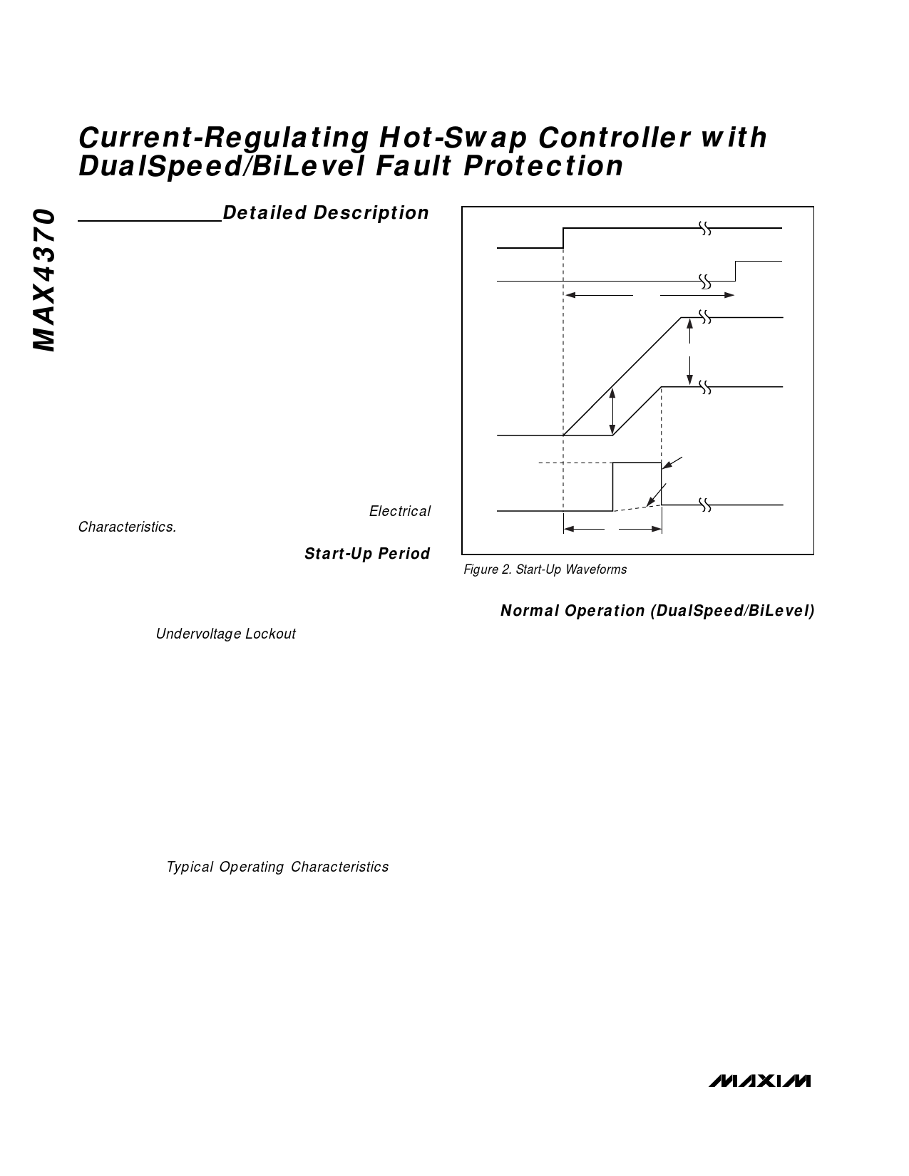
Figure 2 shows the start-up waveforms. STAT goes
high at the end of the start-up period if no fault condi-
tion is present.
ON
STAT
VGATE
VOUT
IFAST, SET
ILOAD
tSTART
~VIN
VTH
tON
CBOARD = LARGE
CBOARD = 0
VGATE
VOUT
Figure 2. Start-Up Waveforms
Normal Operation (DualSpeed/BiLevel)
In normal operation (after the start-up period has
expired), protection is provided by turning off the exter-
nal MOSFET when a fault condition is encountered.
DualSpeed/BiLevel fault protection incorporates two
comparators with different thresholds and response
times to monitor the load current:
1) Slow Comparator. This comparator has an externally
set response time (20µs to seconds) and a fixed
50mV threshold voltage. The slow comparator
ignores low-amplitude momentary current glitches.
After an extended overcurrent condition, a fault is
detected and the MOSFET gate is discharged.
2) Fast Comparator. This comparator has a fixed
response time and a higher 200mV threshold volt-
age. The fast comparator turns off the MOSFET
immediately after it detects a large amplitude event
such as a short circuit.
In each case, when a fault is encountered, the status
pin (STAT) goes low and the MAX4370 stays latched
off. Figure 3 shows the waveforms after a fault condi-
tion.
8 _______________________________________________________________________________________
Share Link: