1N5283 Просмотр технического описания (PDF) - Motorola => Freescale
Номер в каталоге
Компоненты Описание
производитель
1N5283 Datasheet PDF : 5 Pages
| |||
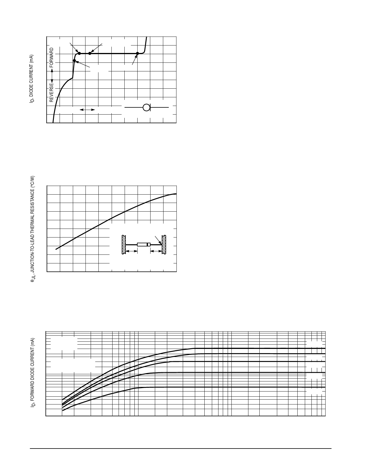
1N5283 through 1N5314
5
4 ZK @ VK
3
2
1
0
–20
IP & ZT @ VT
VL @ IL
POV
–40
–60
–80
–100
–2
REVERSE
FORWARD
+
ANODE
–
CATHODE
–1 0 20 40 60 80 100 120 140 160
VAK, ANODE-CATHODE VOLTAGE (VOLTS)
Figure 1. Typical Current Regulator
Characteristics
300
250
200
POINT OF LEAD TEMPERATURE
MEASUREMENT
150
100
50
0
L
L
(MOST HEAT CONDUCTION IS
THROUGH THE CATHODE LEAD)
0.2
0.4
0.6
0.8
1
L, LEAD LENGTH (INCHES)
Figure 2. Typical Thermal Resistance
10
7
5
TJ = 25°C
POV = 100 V
3
2 (DATA OBTAINED
FROM PULSE TESTS)
1
0.7
0.5
0.3
0.2
SYMBOLS AND DEFINITIONS
ID — Diode Current.
IL — Limiting Current: 80% of IP minimum used to determine
Limiting voltage, VL.
IP — Pinch-off Current: Regulator current at specified Test
Voltage, VT.
POV — Peak Operating Voltage: Maximum voltage to be applied
to device.
θl — Current Temperature Coefficient.
VAK — Anode-to-cathode Voltage.
VK — Knee Impedance Test Voltage: Specified voltage used to
establish Knee Impedance, ZK.
VL — Limiting Voltage: Measured at IL, VL, together with Knee
AC Impedance, ZK, indicates the Knee characteristics of
the device.
VT — Test Voltage: Voltage at which IP and ZT are specified.
ZK — Knee AC Impedance at Test Voltage: To test for ZK, a 90
Hz signal VK with RMS value equal to 10% of test voltage,
VK, is superimposed on VK:
ZK = VK/iK
where iK is the resultant ac current due to VK.
To provide the most constant current from the diode, ZK
should be as high as possible; therefore, a minimum value
of ZK is specified.
ZT — AC Impedance at Test Voltage: Specified as a minimum
value. To test for ZT, a 90 Hz signal with RMS value equal
to 10% of Test Voltage VT, is superimposed on VT.
APPLICATION NOTE
As the current available from the diode is temperature dependent,
it is necessary to determine junction temperature, TJ, under specific
operating conditions to calculate the value of the diode current. The
following procedure is recommended:
Lead Temperature, TL, shall be determined from:
TL = θLA PD + TA
where θLA is lead-to-ambient thermal resistance
and PD is power dissipation.
θLA is generally 30–40°C/W for the various clips and tie points
in common use, and for printed circuit-board wiring.
Junction Temperature, TJ, shall be calculated from:
TJ = TL + θJL PD
where θJL is taken from Figure 2.
For circuit design limits of VAK, limits of PD may be estimated and
extremes of TJ may be computed. Using the information on Figures
4 and 5, changes in current may be found. To improve current
regulation, keep VAK low to reduce PD and keep the leads short,
especially the cathode lead, to reduce θJL.
1N5313
1N5309
1N5305
1N5298
1N5290
0.1
0.1
0.2 0.3
0.5 0.7 1
2
3
5 7 10
VAK, ANODE-CATHODE VOLTAGE (VOLTS)
Figure 3. Typical Forward Characteristics
20
30
50 70 100
1.5 Watt DC Power Data Sheet
9-4
Motorola TVS/Zener Device Data
Share Link: 