UCB1510DB Просмотр технического описания (PDF) - Philips Electronics
Номер в каталоге
Компоненты Описание
производитель
UCB1510DB Datasheet PDF : 32 Pages
| |||
Philips Semiconductors
UCB1510
AC97 digital modem codec
11. Register definition
11.1 Supported registers
Table 5: Supported registers
Register
Name
0x00 to 0x3A
All audio registers are ignored
0x3C
Extended Modem ID
0x3E
Extended Modem Status and Control
0x40
Line1 DAC/ADC Rate
0x42 and 0x44
Reserved for future use
0x46
Line1 DAC/ADC Level
0x48 and 0x4A
Reserved for future use
0x4C
GPIO Pin Configuration
0x4E
GPIO Pin Polarity
0x50
GPIO Pin Sticky
0x52
GPIO Pin Wake-up Mask
0x54
GPIO Pin Status
0x56
Miscellaneous Modem AFE Status and Control
0x58
Ignored
0x5A
Codec control
0x5C
Mode control
0x5E
Test control
0x5E to 0x7A
Ignored
0x7C
Vendor ID1
0x7E
Vendor ID2
11.2 Register detail
Shaded areas indicate read only data.
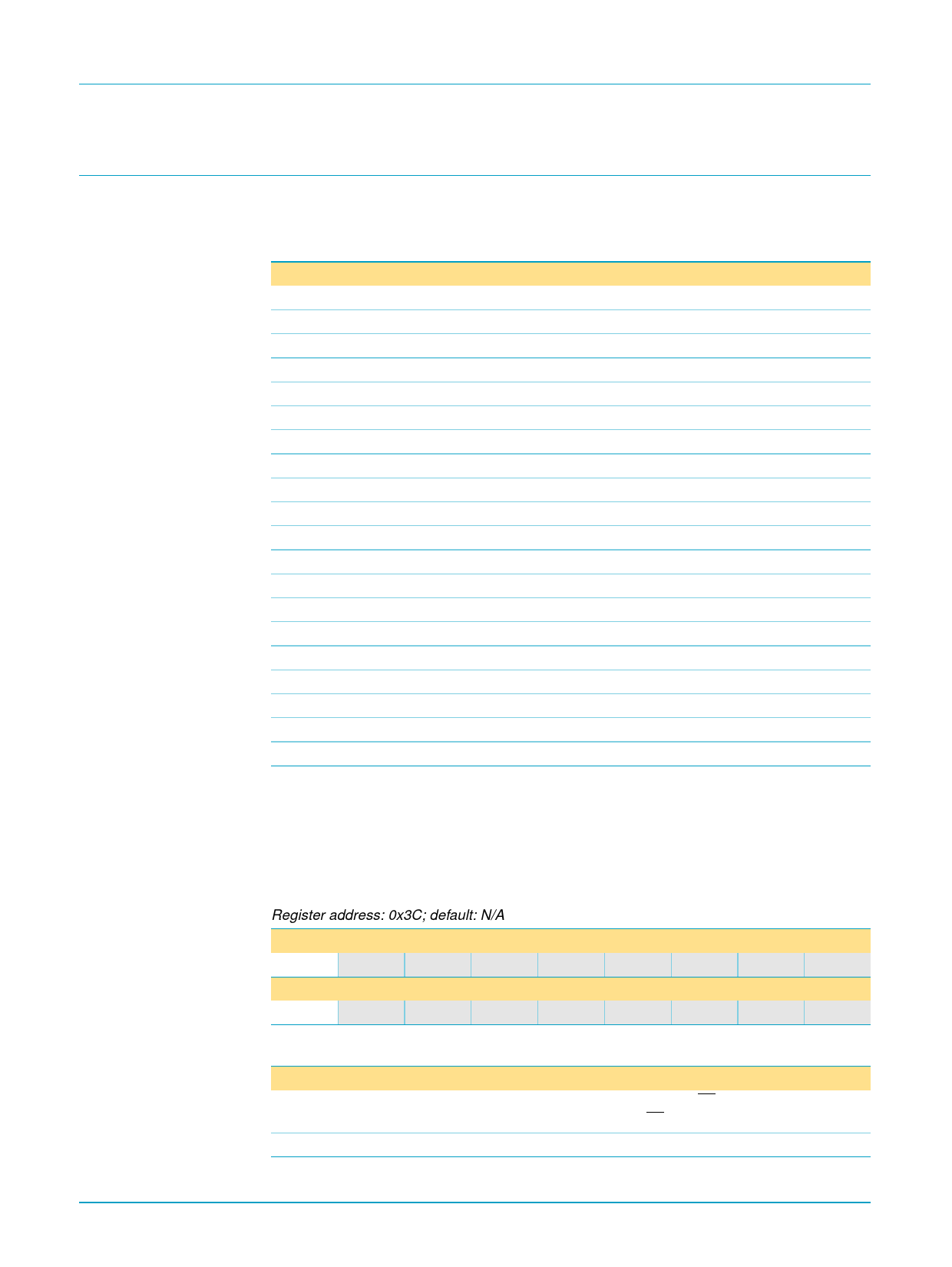
11.2.1 Extended Modem ID
Table 6: Extended Modem ID Register
Register address: 0x3C; default: N/A
Bit
D15
D14
D13
D12
D11
D10
D9
D8
Symbol ID1
ID0
Bit
D7
D6
D5
D4
D3
D2
D1
D0
Symbol
0
0
0
0
LIN1
9397 750 06856
Preliminary specification
Table 7: Description of Extended Modem ID bits
Bit
Symbol Function/Value
D15:14 ID[1:0] {A1,A0} where A0 is the inverse polarity of the A0 pin. A1 is the inverse
polarity of XTAL_IN pin if A0 is HIGH (A0 pin is LOW), otherwise A1 is 0.
D0
LIN1 Line 1 support indicator = 1 (i.e., Line 1 is supported).
[1] Writing this register will cause a register reset: all modem registers will then take their default values.
Rev. 01 — 4 February 2000
© Philips Electronics N.V. 2000. All rights reserved.
9 of 32
Share Link: 