UCB1510DB Просмотр технического описания (PDF) - Philips Electronics
Номер в каталоге
Компоненты Описание
производитель
UCB1510DB Datasheet PDF : 32 Pages
| |||
Philips Semiconductors
UCB1510
AC97 digital modem codec
7. Functional description
The functional description of the devices id described in Section 8 through
Section 15.
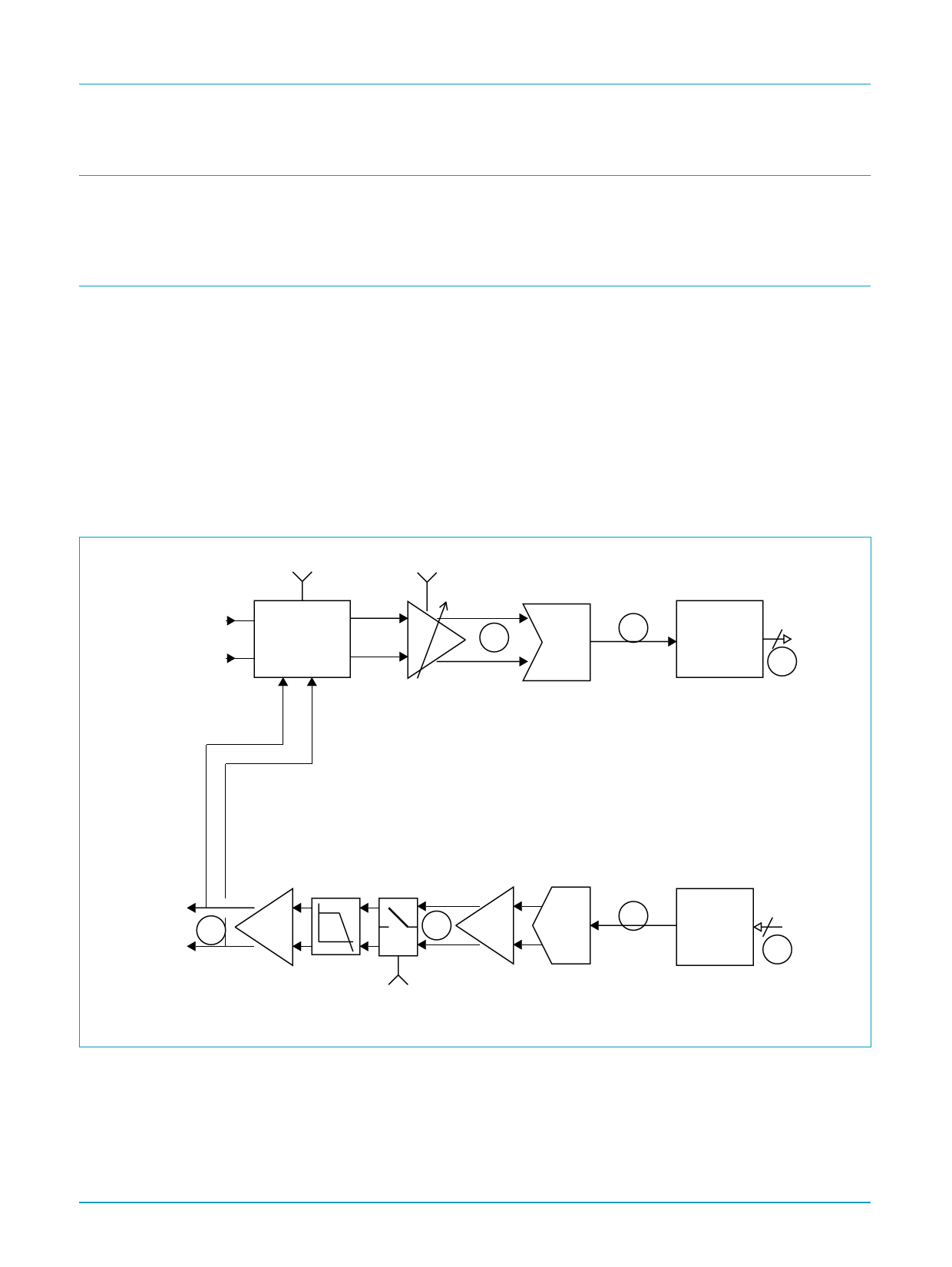
8. Telecom codec
The telecom codec contains an input channel, built up from a 64 times oversampling
sigma delta analog to digital converter (ADC) with digital decimation filters,
programmable gain and attenuation and built-in sidetone suppression circuit.
The output path consists of a digital up sample filter, a 64 time oversampling 4 bit
digital to analog converter (DAC) circuit with integrated filter followed by a differential
output driver, capable of directly driving a 600 Ω isolation transformer. The output
path includes a mute function. The telecom codec also incorporates loop back
modes, in which codec output path and the input path are connected in series. The
loop back tap and entry points are identified as circled letters in Figure 3, loop back
modes are described in the AClink register definition.
sidetone_enable
ADC[3:2]
TINP
TINN
SIDETONE
SUPPRESSION
CIRCUIT
ADC
J
H
DIGITAL
14
DECIMATION
FILTER
G
TOUTP
E
TOUTN
D
DAC
C
DIGITAL
14
NOISE
SHAPER
B
DAC Mute
Fig 3. Telecom codec block diagram
9397 750 06856
Preliminary specification
The telecom sample rate (fst) is derived from the AC master clock and is
programmable using the sample rate registers. Not all AC97 specified sample rates
are supported, refer to Table 3 “Sampling frequencies” for details.
PCM data is transferred in the slot 5 of the AClink.
Rev. 01 — 4 February 2000
© Philips Electronics N.V. 2000. All rights reserved.
5 of 32
Share Link: 