UC3842B(2013) Просмотр технического описания (PDF) - ON Semiconductor
Номер в каталоге
Компоненты Описание
производитель
UC3842B Datasheet PDF : 22 Pages
| |||
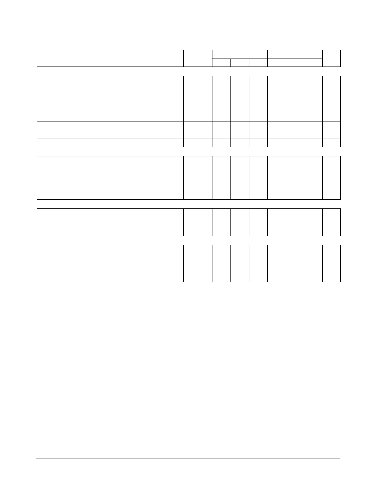
UC3842B, UC3843B, UC2842B, UC2843B
ELECTRICAL CHARACTERISTICS (VCC = 15 V [Note 7], RT = 10 k, CT = 3.3 nF. For typical values TA = 25°C, for min/max values
TA is the operating ambient temperature range that applies [Note 8], unless otherwise noted.)
UC284XB, UC2843D
UC384XB, XBV
Characteristics
Symbol Min Typ Max Min Typ Max Unit
CURRENT SENSE SECTION
Current Sense Input Voltage Gain (Notes 5 and 6)
AV
UC2843D, UC284XB, UC384XB
UC384XBV
V/V
2.85 3.0 3.15 2.85 3.0 3.15
−
−
− 2.85 3.0 3.25
Maximum Current Sense Input Threshold (Note 5)
Vth
UC2843D, UC284XB, UC384XB
UC384XBV
V
0.9 1.0 1.1 0.9 1.0 1.1
−
−
− 0.85 1.0 1.1
Power Supply Rejection Ratio (VCC = 12 V to 25 V, Note 5)
PSRR
−
70
−
−
70
−
dB
Input Bias Current
IIB
− − 2.0 −10
− − 2.0 −10 mA
Propagation Delay (Current Sense Input to Output)
tPLH(In/Out)
−
150 300
−
150 300 ns
OUTPUT SECTION
Output Voltage
Low State (ISink = 20 mA)
(ISink = 200 mA)
High State (ISource = 20 mA)
(ISource = 200 mA)
VOL
UC284XB, UC384XB
UC384XBV, UC2843D
UC284XB, UC384XB
VOH
UC384XBV, UC2843D
V
−
0.1 0.4
−
0.1 0.4
−
1.6 2.2
−
1.6 2.2
−
−
−
−
1.6 2.3
13 13.5 −
13 13.5 −
−
−
− 12.9 13.5 −
12 13.4 −
12 13.4 −
Output Voltage with UVLO Activated (VCC = 6.0 V, ISink = 1.0 mA) VOL(UVLO) −
0.1 1.1
−
0.1 1.1 V
Output Voltage Rise Time (CL = 1.0 nF, TJ = 25°C)
tr
−
50 150
−
50 150 ns
Output Voltage Fall Time (CL = 1.0 nF, TJ = 25°C)
tf
−
50 150
−
50 150 ns
UNDERVOLTAGE LOCKOUT SECTION
Startup Threshold (VCC)
Vth
UCX842B, BV
UCX843B, BV, D
V
15
16
17 14.5 16 17.5
7.8 8.4 9.0 7.8 8.4 9.0
Minimum Operating Voltage After Turn−On (VCC)
VCC(min)
V
UCX842B, BV
9.0
10
11
8.5
10 11.5
UCX843B, BV, D
7.0 7.6 8.2 7.0 7.6 8.2
PWM SECTION
Duty Cycle
Maximum UC284XB, UC384XB, UC2843D
Maximum UC384XBV
Minimum
%
DC(max)
94
96
−
94
96
−
−
−
−
93
96
−
DC(min)
−
−
0
−
−
0
TOTAL DEVICE
Power Supply Current
Startup (VCC = 6.5 V for UCX843B, UC2843D
Startup VCC 14 V for UCX842B, BV)
(Note 7)
ICC + IC
mA
−
0.3 0.5
−
0.3 0.5
−
12
17
−
12
17
Power Supply Zener Voltage (ICC = 25 mA)
VZ
30
36
−
30
36
−
V
5. This parameter is measured at the latch trip point with VFB = 0 V.
6. Comparator gain is defined as: AV
DV Output Compensation
DV Current Sense Input
7. Adjust VCC above the Startup threshold before setting to 15 V.
8. Low duty cycle pulse techniques are used during test to maintain junction temperature as close to ambient as possible.
Tlow = 0°C for UC3842B, UC3843B; −25°C for UC2842B, UC2843B; −40°C for UC3842BV, UC3843BV, UC2843D
Thigh = +70°C for UC3842B, UC3843B; +85°C for UC2842B, UC2843B, UC2843D; +105°C for UC3842BV, UC3843BV
http://onsemi.com
4
Share Link: 