TS7514 Просмотр технического описания (PDF) - STMicroelectronics
Номер в каталоге
Компоненты Описание
производитель
TS7514 Datasheet PDF : 19 Pages
| |||
TS7514
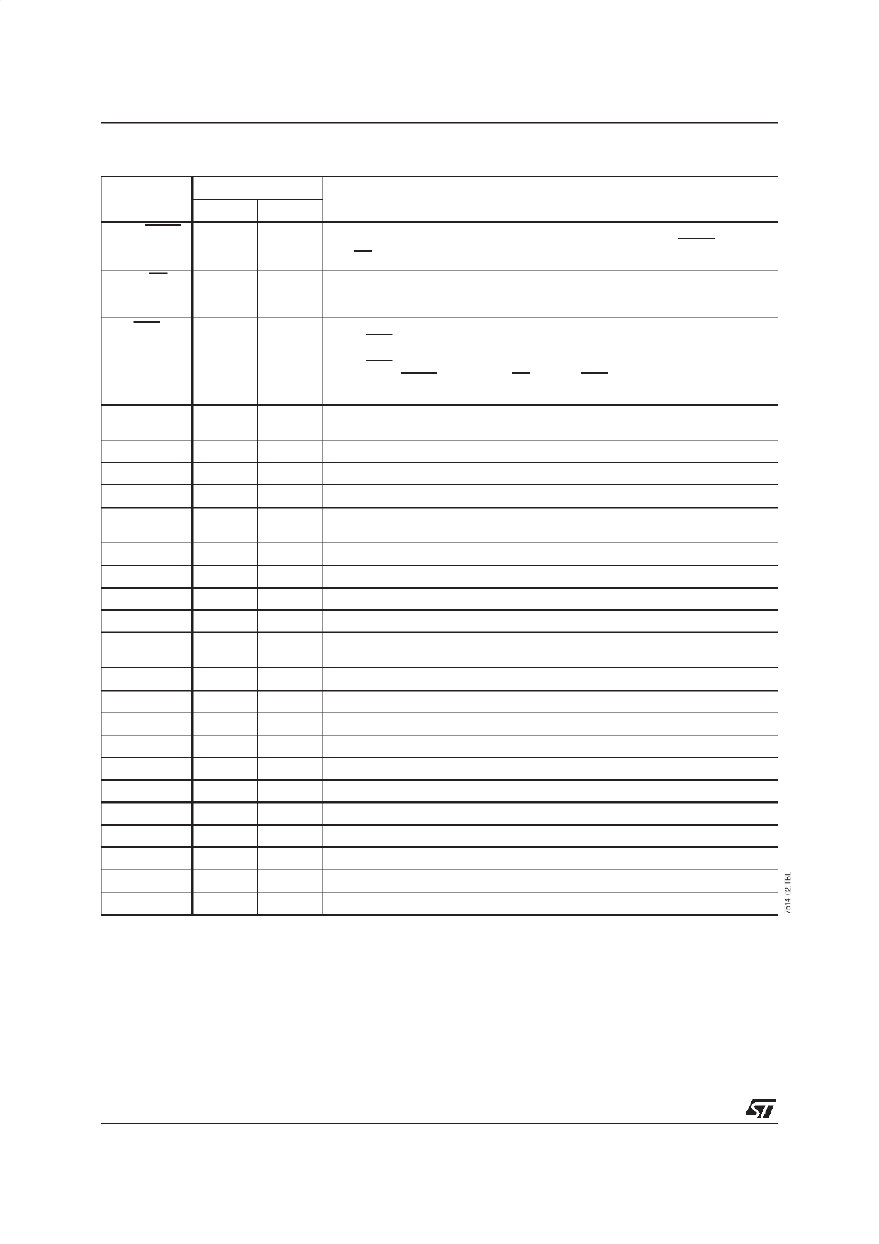
PIN DESCRIPTION
Name
MOD/DMTF
MC/BC
RTS
ENP
DGND
TxD
PRD
XtaIIN
XtaIOUT
DCD
RxD
ZCO
RDI
RFO
RAO2
RAI2
RAI1
RAO1
V-
AGND
V+
ATO
WLO
ATxI
Pin Number
DIP24 PLCC28
1
1
2
3
3
4
4
5
5
6
6
7
7
8
8
10
9
11
10
13
11
14
12
15
13
16
14
17
15
18
16
20
17
21
18
22
19
23
20
24
21
25
22
26
23
27
24
28
Description
MODEM or DMTF Operating Mode Selection.
Also controls write operations to control registers (if MOD/DMTF = 0 and
MC/BC = 0).
Digital Control Input.
In MODEM mode, it sets transmission mode to main or back channel. It also
permits selection of dialing or control registers programming.
Request to Send.
When RTS = 0, the circuit sends an analog signal to the ATO output. The signal
depends on the operating mode selected.
When RTS = 1, the signal sent to ATO is suppressed after its first zero crossing.
When MOD/DMTF = 0 and MC/BC = 0, the RTS pin acts as a clock for serial
data loading into the input register.
Serial Register Write Select Input. When ENP = 0, the serial register input is
connected to TxD. When ENP = 1, the register input is connected to PRD.
Digital Ground = 0V. All digital signals are referenced to this pin.
Digital Input for Transmit or Control Data
Digital Input for Control Data. Selected through ENP
Crystal Oscillator Input. Can be tied to an external clock generator.
fQUARTZ = 3.579MHz.
Crystal Oscillator Output
Data Carrier Detect Output
Digital Receive Data Output
Zero Crossing Rx Digital Output (ringing detection)
Analog Output for the Receive Signal after Filtering or Analog Input for the
Amplifier-limiter.
Analog Receive Filter Output
A2 Amplifier Output
A2 Amplifier Inverting Input
A1 Amplifier Inverting Input
A1 Amplifier Output
Negative Supply Voltage : – 5V ±5%
Analog Ground = 0 V. Reference Pin for Analog Signals
Positive Supply Voltage : + 5V ±5%
Analog Transmit Output
Analog Output for Line Monitoring and Buzzer
Direct Analog Input Transmit Filter
2/19
Share Link: 