ACT15530PC Просмотр технического описания (PDF) - Aeroflex Corporation
Номер в каталоге
Компоненты Описание
производитель
ACT15530PC Datasheet PDF : 15 Pages
| |||
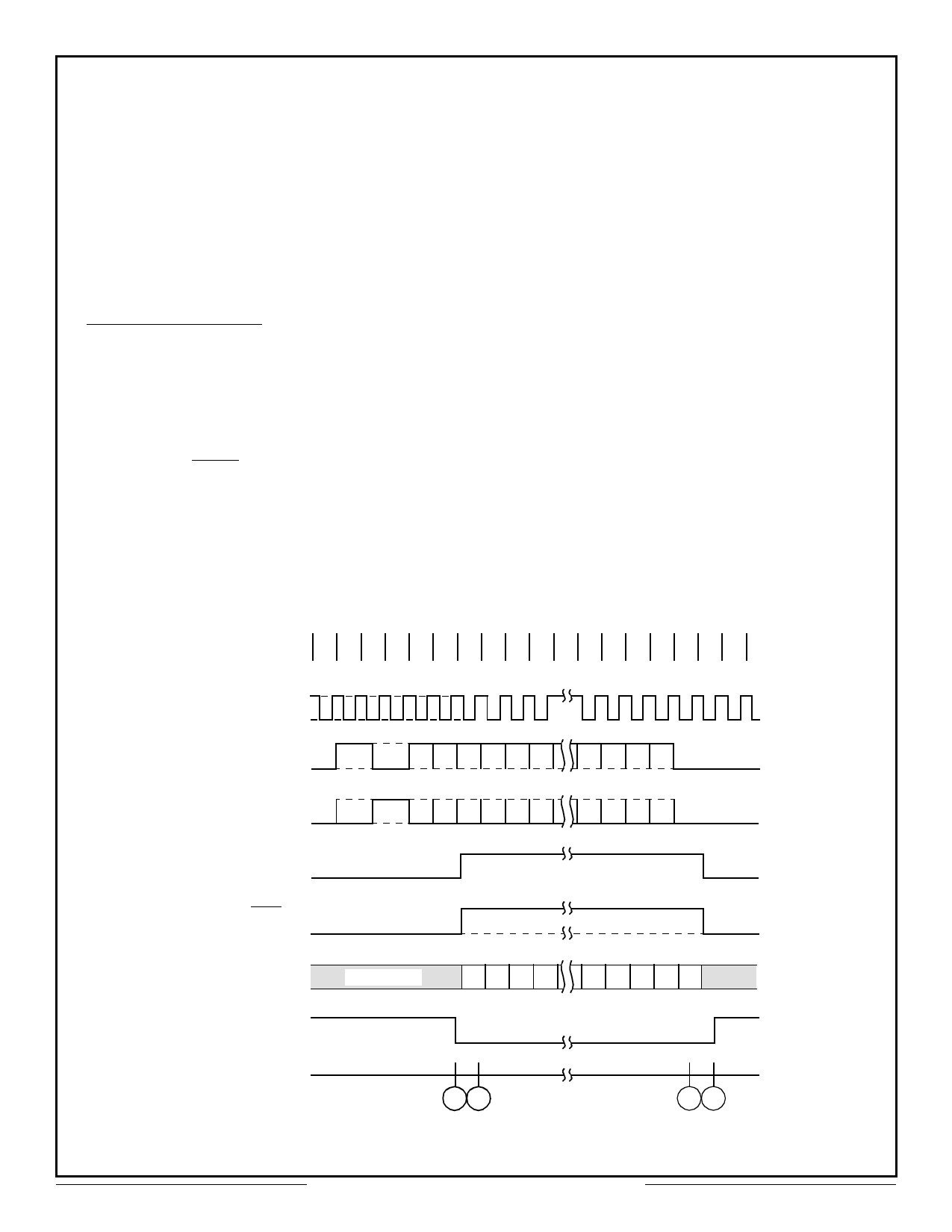
Decoder Operation
The Decoder requires a single clock with a
frequency of 12 times the desired data rate
applied at the DECODER CLOCK input. The
Manchester II coded data can be presented to the
Decoder in one of two ways. The BIPOLAR
ONE and BIPOLAR ZERO inputs will accept
data from a comparator sensed transformer
coupled bus as specified in MIL-STD-1553. The
UNIPOLAR DATA input can only accept
non-inverted Manchester II coded data (e.g.from
BIPOLAR ZERO OUT of an Encoder).
The Decoder is free running and continuously
monitors its data input lines for a valid sync
character and two valid Manchester data bits to
start an output cycle.. When a valid sync is
recognized x, the type of sync is indicated on
COMMAND/DATA SYNC output. if the sync
character was a command sync, this output will
go high y and remain high for sixteen
DECODER SHIFT CLOCK periods z,
otherwise it will remain low. The TAKE DATA
output will go high and remain high y - z
while the Decoder is transmitting the decoded
data through SERIAL DATA OUT. The decoded
data available at SERIAL DATA OUT is in a
NRZ format. The DECODER SHIFT CLOCK is
provided so that the decoded bits can get shifted
into an external register on every low-to-high
transition of this clock y - z.
After all sixteen decoded bits have been
transmitted z the data is checked for odd parity.
A high on VALID WORD output { indicates a
successful reception of a word without any
Manchester or parity errors. At this time the
Decoder is looking for a new sync character to
start another output sequence.
At any time in the above sequence, a high
input on DECODER RESET during a
low-to-high transition of DECODER SHIFT
CLOCK will abort transmission and initialize
the Decoder to start looking for a new sync
character.
Timing
0 1 2 3 4 5 6 7 8 16 17 18 19
Decoder
Shift Clock
Bipolar
One In
Bipolar
Zero In
Take Data
Command/Data
Sync
Serial Data Out
1st 2nd 15 14 13 12 11 10
Half Half
Sync Sync 15 14 13 12 11 10
210 P
210 P
Undefined
15 14 13 12
43210
Valid Word
(From Previous
Reception)
12
34
Aeroflex Circuit Technology
Figure 10: Decoder Operation
7
SCD15530 REV B 7/28/99 Plainview NY (516) 694-6700
Share Link: 