TEA1205 Просмотр технического описания (PDF) - Philips Electronics
Номер в каталоге
Компоненты Описание
производитель
TEA1205 Datasheet PDF : 16 Pages
| |||
Philips Semiconductors
High efficiency DC/DC converter
Preliminary specification
TEA1205AT
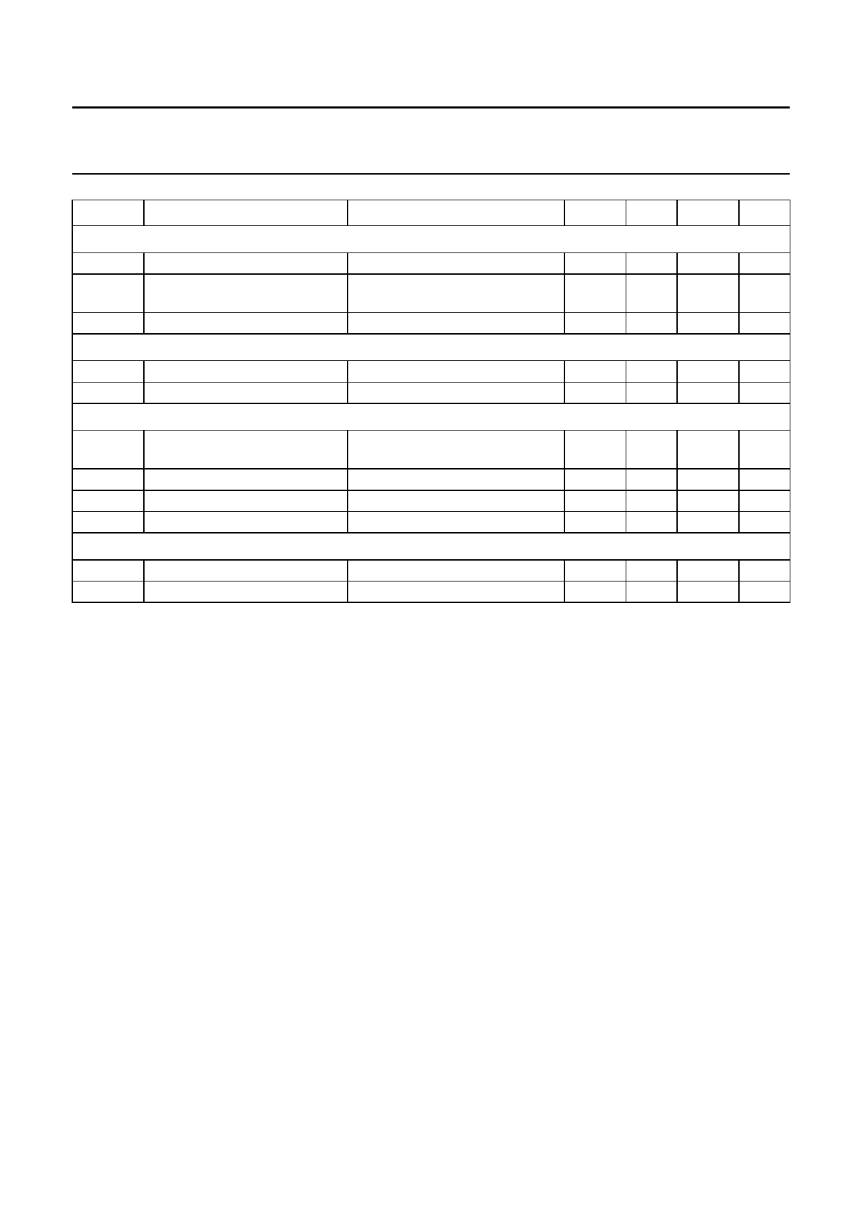
SYMBOL
PARAMETER
CONDITIONS
MIN. TYP. MAX. UNIT
Timing
fsw
switching frequency
tres
response time from standby to
Pmax
fsync
synchronisation input frequency
Temperature
Tamb
Tmax
operating ambient temperature
internal cut-off temperature
Digital levels
VlL
LOW-level input voltage pins
1, 2, 7 and 8
VIH
HIGH-level input voltage pin 1 note 2
VIH
HIGH-level input voltage pin 2 notes 2 and 3
VIH
HIGH-level input voltage pin 8 notes 2 and 3
Sense pin resistance
RSENSE
SENSE pin resistance to GND up to 3.3 V mode
up to 5.0 V mode
150
200 240
kHz
−
25
−
µs
−
13
−
MHz
−20
+25 +80
°C
150
165 180
°C
0
−
V3 − 0.4 −
2.0
−
2.9
−
0.4
V
V3 + 0.3 V
V3 + 0.3 V
V3 + 0.3 V
437.2 546.5 655.8 kΩ
662.2 827.8 993.4 kΩ
Notes
1. The NFET current limit is set by an external 1% accurate resistor Rlim connected between pin 7 and pin 6 (ground).
The typical maximum instantaneous current is defined as: Ilim = 890 V/ Rlim so the use of Rlim = 315 Ω will lead to a
typical maximum current value of 2.83 A. The average inductor current during current limit also depends on
inductance value and resistive losses in all components in the power path. In normal application and when using
Rlim = 315 Ω, the average inductor current will be limited to 2.3 A typical.
2. V3 is the voltage at pin 3 (OUT).
3. If the applied high level is less than V3 − 1 V, the quiescent current level of the device will increase. The maximum
increase is 300 µA in the event that pin 2 is at 2.0 V.
1998 Mar 24
9
Share Link: 