TC7129CPL Просмотр технического описания (PDF) - Microchip Technology
Номер в каталоге
Компоненты Описание
производитель
TC7129CPL Datasheet PDF : 28 Pages
| |||
3.5 Voltage Reference
(DREF, RREF, RBIAS, CRF)
The reference potentiometer (RREF) provides an
adjustment for adjusting the reference voltage; any
value above 20 kΩ is adequate. The bias resistor
(RBIAS) limits the current through DREF to less than
150 μA. The reference filter capacitor (CRF) forms an
RC filter with RBIAS to help eliminate noise.
3.6 Input Filter (RIF, CIF)
For added stability, an RC input noise filter is usually
included in the circuit. The input filter resistor value
should not exceed 100 kΩ. A typical RC time constant
value is 16.7 msec to help reject line frequency noise.
The input filter capacitor should have low leakage for a
high-impedance input.
3.7 Battery
The typical circuit uses a 9V battery as a power source.
However, any value between 6V and 12V can be used.
For operation from batteries with voltages lower than
6V and for operation from power supplies, see
Section 4.2 “Powering the TC7129”.
4.0 TYPICAL APPLICATIONS
4.1 TC7129 as a Replacement Part
The TC7129 is a direct pin-for-pin replacement part for
the ICL7129. Note, however, that the ICL7129 requires
a capacitor and resistor between pins 26 and 28 for
phase compensation. Since the TC7129 uses internal
phase compensation, these parts are not required and,
in fact, must be removed from the circuit for stable
operation.
4.2 Powering the TC7129
While the most common power source for the TC7129
is a 9V battery, there are other possibilities. Some of
the more common ones are explained below.
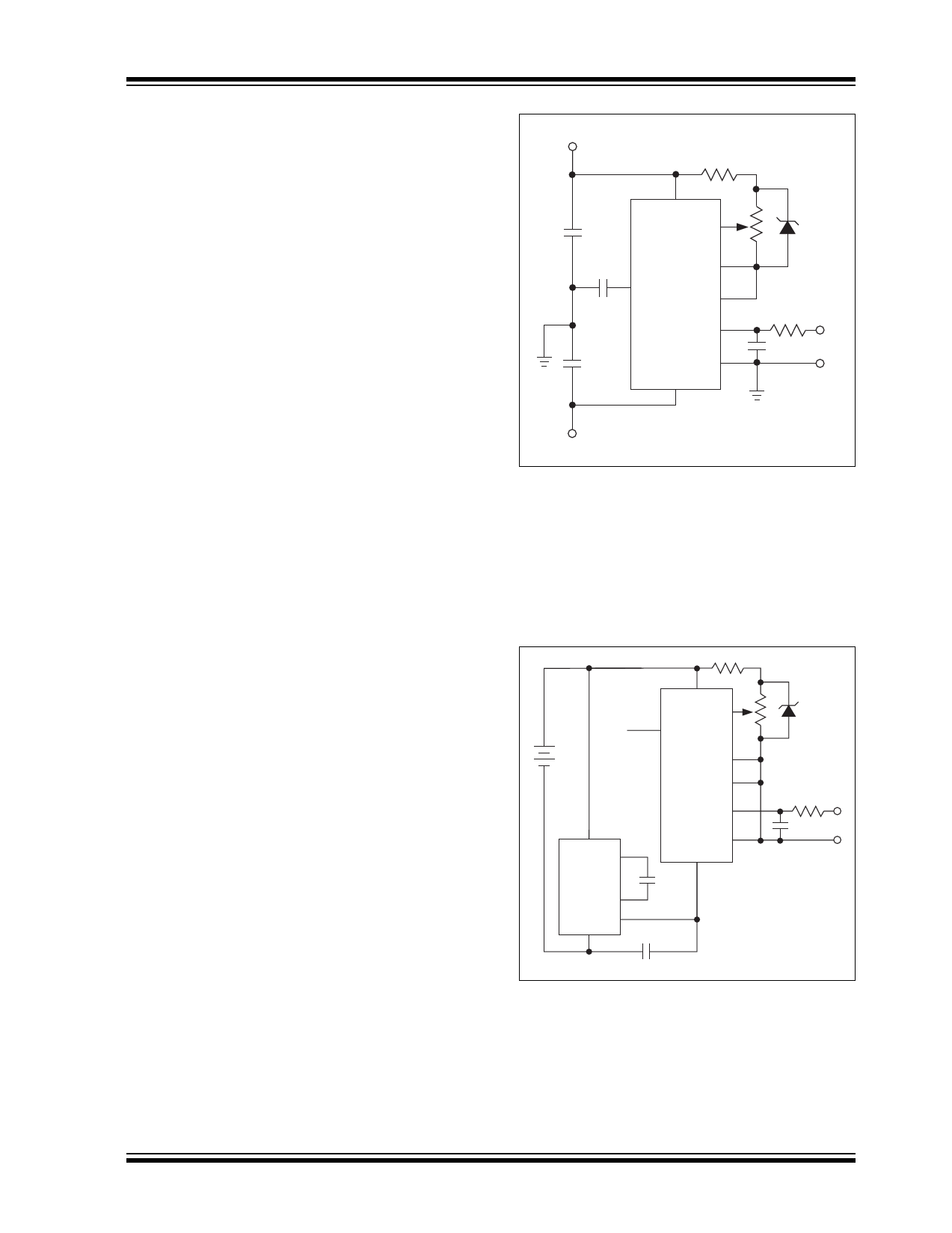
4.2.1 ±5V Power Supply
Measurements are made with respect to power supply
ground. DGND (pin 36) is set internally to about 5V less
than V+ (pin 24); it is not intended to be a power supply
input and must not be tied directly to power supply
ground. It can be used as a reference for external logic,
as explained in Section 4.3 “Connecting to External
Logic”, (see Figure 4-1).
TC7129
+5V
TC7129
0.1 µF
24
V+
34
REF HI
35
REF LO
36
0.1 µF
DGND
COMMON
28
IN HI 33
0.1 µF
IN LO 32
V–
23
+
VIN
–
-5V
Figure 4-1:
Powering the TC7129 From
a ±5V Power Supply.
4.2.2 Low Voltage Battery Source
A battery with voltage between 3.8V and 6V can be
used to power the TC7129 when used with a voltage
doubler circuit, as shown in Figure 4-2. The voltage
doubler uses the TC7660 DC-to-DC voltage converter
and two external capacitors.
24
+
3.8V
to
6V
V+
34
REF HI
36 DGND
REF LO 35
COMMON 28
TC7129
33
+
IN HI
8
2
IN LO 32
V–
VIN
–
+
23
TC7660
10 µF
4
5
3
10 µF
+
Figure 4-2:
Powering the TC7129 From
a Low-Voltage Battery.
© 2006 Microchip Technology Inc.
DS21459D-page 9
Share Link: 