TC7129 Просмотр технического описания (PDF) - Microchip Technology
Номер в каталоге
Компоненты Описание
производитель
TC7129 Datasheet PDF : 28 Pages
| |||
TC7129
V+
V+
1N4148
5 kΩ
75 kΩ
39 kΩ
200 kΩ
24
TC7129
–
+
19 VDISP
36 DGND
23
39 kΩ
24
20 kΩ
2N2222 TC7129
18 kΩ
19
VDISP
36
DGND
23
V–
V–
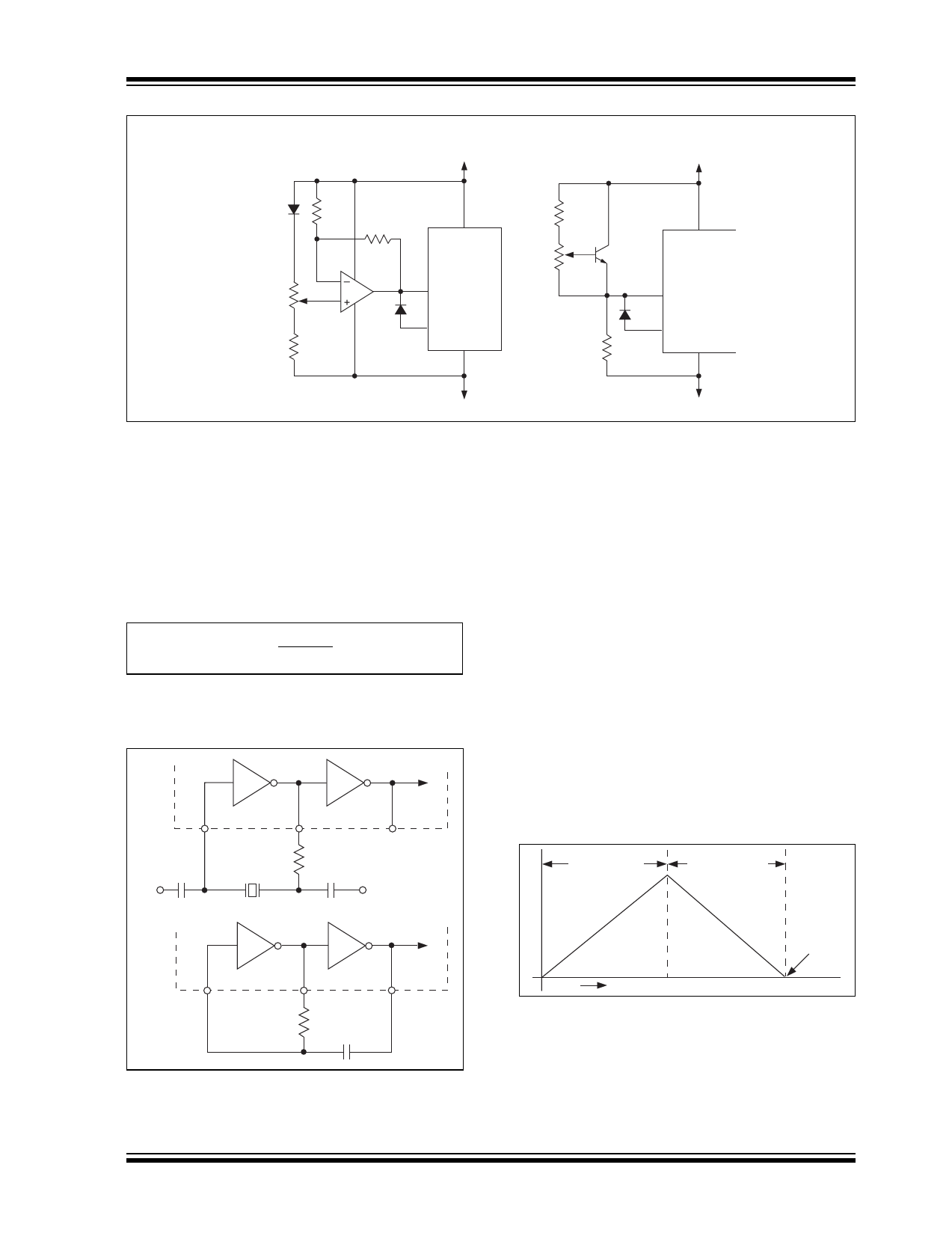
Figure 4-6:
Temperature Compensating Circuits.
4.5 RC Oscillator
For applications in which 3-1/2 digit (100 μV) resolution
is sufficient, an RC oscillator is adequate. A recom-
mended value for the capacitor is 51 pF. Other values
can be used as long as they are sufficiently larger than
the circuit parasitic capacitance. The resistor value is
calculated as:
EQUATION 4-1:
R = 0.45
Freq * C
For 120 kHz frequency and C = 51 pF, the calculated
value of R is 75 kΩ. The RC oscillator and the crystal
oscillator circuits are shown in Figure 4-7.
1
5 pF
V+
120 kHz
40
270 kΩ
10 pF
TC7129
2
V+
4.6 Measuring Techniques
Two important techniques are used in the TC7129:
successive integration and digital auto-zeroing.
Successive integration is a refinement to the traditional
dual-slope conversion technique.
4.7 Dual-Slope Conversion
A dual-slope conversion has two basic phases: inte-
grate and de-integrate. During the integrate phase, the
input signal is integrated for a fixed period of time; the
integrated voltage level is thus proportional to the input
voltage. During the de-integrate phase, the integrated
voltage is ramped down at a fixed slope, and a counter
counts the clock cycles until the integrator voltage
crosses zero. The count is a measurement of the time
to ramp the integrated voltage to zero and is, therefore,
proportional to the input voltage being measured. This
count can then be scaled and displayed as a measure-
ment of the input voltage. Figure 4-8 shows the phases
of the dual-slope conversion.
Integrate
De-integrate
1
Figure 4-7:
40
75 kΩ
51 pF
TC7129
2
Oscillator Circuits.
Zero
Crossing
Time
Figure 4-8:
Dual-Slope Conversion.
The dual-slope method has a fundamental limitation.
The count can only stop on a clock cycle, so that mea-
surement accuracy is limited to the clock frequency. In
addition, a delay in the zero-crossing comparator can
add to the inaccuracy. Figure 4-9 shows these errors in
an actual measurement.
© 2006 Microchip Technology Inc.
DS21459D-page 11
Share Link: 