PC904 Просмотр технического описания (PDF) - Sharp Electronics
Номер в каталоге
Компоненты Описание
производитель
PC904 Datasheet PDF : 6 Pages
| |||
PC904
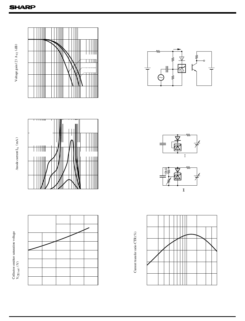
Fig.18-b Voltage Gain (2) vs. Frequency
10
IA = 2mA
IC = 1.7mA
0
T a = 25˚C
- 10
RL = 10k Ω
- 20
1k Ω
100 Ω
- 30
- 40
Test Circuit for Voltage Gain (2) vs.
Frequency
620 Ω
IA
10k Ω
10 µF
Vin
f
10
kΩ
RL
Vo
- 50
0.1
1
10
100
Frequency f ( kHz)
1 000
Fig.19 Anode Current vs. Load Capacitance
50
A••• VK = VREF
B••• VA = 5V
( at I A = 10mA)
40 C••• VA = 10V
( at I A = 10mA)
D••• VA = 15V
( at I A = 10mA) A
30
Oscilating
area
T a = 25˚C
B
B
A
Stable area
20
Stable area
C
Test Circuit for Anode Current vs.
Load Capacitance
150 Ω
CL
Test circuit (A)
150 Ω
10
CL
D
0
10 - 3
10 - 2
10 - 1
1
10
Load capacitance C L ( µ F)
Fig.20 Collector-emitter Saturation Voltage
vs. Ambient Temperature
0.16
V K = V REF
0.14 IC = 1mA
0.12 IA = 10mA
0.10
Test circuit ( B, C, D )
Fig.21 Current Transfer Ratio vs.
Anode Current
300
V K = V REF
VCE = 5V
250
T a = 25˚C
200
0.08
150
0.06
100
0.04
50
0.02
0
- 25
0
25
50
75
100
0
1
2
5
10 20
50
Ambient temperature T a (˚C)
Anode Current IA ( mA )
s Precautions for Use
Handle this product the same as with other integrated circuits against static electricity.
q As for other general cautions, refer to the chapter “ Precautions for Use ”
Share Link: 