STK672-740B-E Просмотр технического описания (PDF) - SANYO -> Panasonic
Номер в каталоге
Компоненты Описание
производитель
STK672-740B-E Datasheet PDF : 23 Pages
| |||
STK672-740B-E
2. STK672-740B-E overcurrent detection, overheat detection, and motor terminal open detection functions
Each detection function operates using a latch system and turns output off. Because a RESET signal is required to
restore output operations, once the power supply, VDD, is turned off, you must either again apply power on reset
with VDDON or apply a RESETB=High→Low→High signal.
[Motor terminal open detection]
This hybrid IC is equipped with a function for detecting open output terminals to prevent thermal destruction of the
MOSFET due to repeated avalanche operation that occurs when an output terminal connected to the motor is open.
The open condition is determined by checking the presence or absence of the flyback current that flows in the motor
inductance during the off period of the PWM cycle.
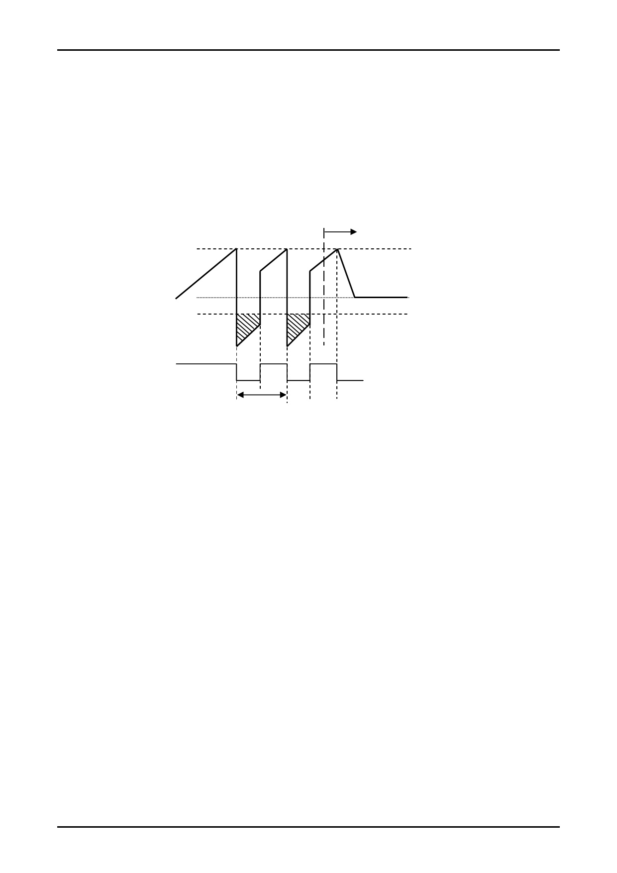
Detection is performed by using the fact that the flyback current does not flow when a motor terminal is open.
Current detection
resistor voltage
Terminal open
Used to set the motor current
0V (GND potential)
Used for open detection
(Negative current does not flow
when the terminal is open.)
MOSFET gate signal
PWM period
When the current level drops, the difference with the GND potential decreases, making detection difficult. The motor
current that can be detected by motor terminal open detection is 1.1A or more with the STK672-740B-E.
<Notes on the ENABLE high edge>
When ENABLE changes from low to high and the STK672-7XXB-E performs constant-current PWM operation
that flows a negative current during the 30μs period after the high edge, open detection may activate and stop the
driver.
The motor current setting voltage Vref must be set so that PWM operation is not performed within a period of 30μs
after the high edge.
If the motor current setup voltage is set for the rated motor current, PWM operation is not performed during this
30μs period after the high edge, so this is not a problem.
In addition, there is no problem with operation that lowers the current setting Vref after the motor rated current is
reached as shown in the diagram on the following page.
Whether constant-current PWM operation is performed during the 30μs period after the high edge can be judged by
substituting the motor L and R values into the formula on the following page.
Vref= (R02÷ (R01+R02)) ×5V (or 3.3V)
IOH1= (Vref÷4.9) ÷Rs
IOH1: Motor current value to be set
IOH2= (VCC÷R) × (1-e-tR/L) IOH2: Current value 30μs after the ENABLE high edge
⇒ Judgment standard: IOH1>IOH2
R01, R02, 5V (or 3.3V): See the Sample Application Circuit documents.
Rs: Current detection resistance value (Ω)
VCC: Motor supply voltage (V)
R: Motor winding resistance (Ω)
L: Motor winding inductance (H)
⇒ There is no problem if the IOH2 obtained by substituting t = 30μs and the motor L and R values is smaller than
the current setting value IOH1.
No. A1932-11/23
Share Link: 