STA515W13TR(2010) Просмотр технического описания (PDF) - STMicroelectronics
Номер в каталоге
Компоненты Описание
производитель
STA515W13TR Datasheet PDF : 14 Pages
| |||
STA515W
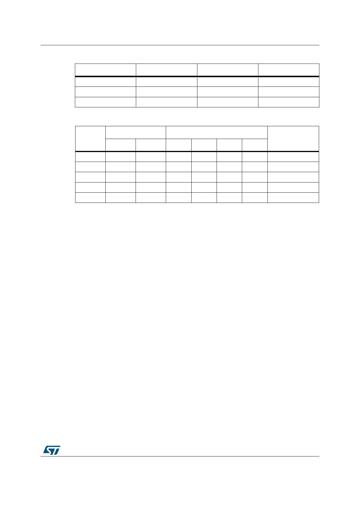
Electrical characteristics
Table 7. Threshold switching voltage variation with voltage on pin VL
Voltage on pin VL, VL
VLOW max
VHIGH min
Unit
2.7
0.7
1.5
V
3.3
0.8
1.7
V
5.0
0.85
1.85
V
Table 8. Logic truth table
Pin
Inputs as per Figure 4
TRISTATE INxA
INxB
Transistors as per Figure 4
Q1
Q2
Q3
Q4
0
x
x
Off
Off
Off
Off
1
0
0
Off
Off
On
On
1
0
1
Off
On
On
Off
1
1
0
On
Off
Off
On
1
1
1
On
On
Off
Off
Output mode
Hi Z
Dump
Negative
Positive
Not used
Test circuits
Figure 3. Test circuit
Low current dead time = MAX(DTr,DTf)
Duty cycle = 50%
INxY
+Vcc
OUTxY
gnd
OUTxY
Vcc
(3/4)Vcc
(1/2)Vcc
(1/4)Vcc
t
DTr
DTf
R 8Ω
+
-
vdc = Vcc/2
D03AU1458
Figure 4.
Current dead time test circuit
High Current Dead time for Bridge application = ABS(DTout(A)-DTin(A))+ABS(DTOUT(B)-DTin(B))
+VCC
Duty cycle=A
DTin(A)
INA
DTout(A)
Q1
OUTA
L67 22µ
Iout=4.5A
Q3
C69
470nF
Rload=8Ω
C71 470nF
Q2
DTout(B)
OUTB
L68 22µ
Iout=4.5A
C70
Q4
470nF
Duty cycle=B
DTin(B)
INB
Duty cycle A and B: Fixed to have DC output current of 4.5A in the direction shown in figure
D03AU1517
Doc ID 11079 Rev 2
7/14
Share Link: 