SPX2920S-5.0 Просмотр технического описания (PDF) - Signal Processing Technologies
Номер в каталоге
Компоненты Описание
производитель
SPX2920S-5.0 Datasheet PDF : 7 Pages
| |||
APPLICATION HINTS
EXTERNAL CAPACITORS
The stability of the SPX2920 requires a 2.2µF or greater
capacitor between output and ground. Oscillation could occur
without this capacitor. Most types of tantalum or aluminum
electrolytic works fine here. For operations of below -25°C solid
tantalum is recommended since the many aluminum types have
electrolytes the freeze at about -30°C. The ESR of about 5Ω or
less and resonant frequency above 500kHz are the most
important parameters in the value of the capacitor. The capacitor
value can be increased without limit.
At lower values of output current, less output capacitance is
required for stability. For the currents below 10mA the value of
the capacitor can be reduced to 0.5µF and 0.15µF for 1mA. More
output capacitance needed for the 8-pin version at voltages below
5V since it runs the error amplifier at lower gain. At worst case
5µF or greater must be used for the condition of 250mA load at
1.23V output.
The SPX2920, unlike other low dropout regulators will remain
stable and in regulation with no load in addition to the internal
voltage divider. This feature is especially important in
application like CMOS RAM keep-alive. When setting the output
voltage of the SPX2920, a minimum load of 10mA is
recommended.
If there is more than 10 inches of wire between the input and the
AC filter capacitor or if a battery is used as the input then a 0.1µF
tantalum or aluminum electrolytic capacitor should be placed
from the input to the ground.
Instability can occur if there is stray capacitance to the SPX2920
feedback terminal (pin 7). This could cause more problems when
using a higher value of external resistors to set the output voltage.
SPX2920
This problem can be fixed by adding a 100pF capacitor between
output and feedback and increasing the output capacitor to at least
3.3µF.
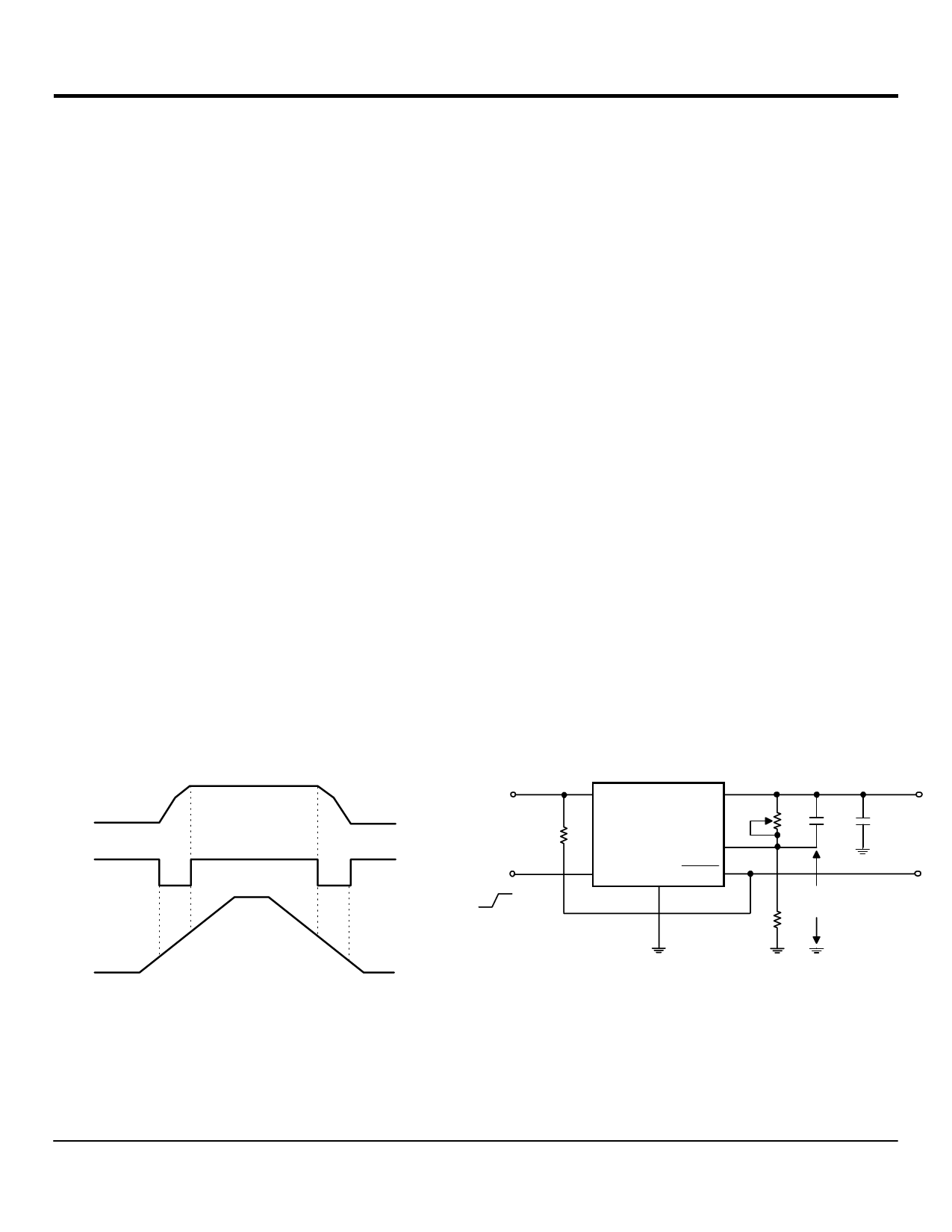
ERROR DETECTION COMPARATOR OUTPUT
The Comparator produces a logic low output whenever the SPX2920
output falls out of regulation by more than around 5%. This is around
60mV offset divided by the 1.235 reference voltage. This trip level
remains 5% below normal regardless of the programmed output
voltage of the regulator. Figure 1 shows the timing diagram depicting
the ERROR signal and the regulator output voltage as the SPX2920
input is ramped up and down. The ERROR signal becomes low at
around 1.3V input, and goes high around 5V input (input voltage at
which Vout = 4.75). Since the SPX2920’s dropout voltage is load
dependent, the input voltage trip point (around 5V) will vary with the
load current. The output voltage trip point (approx. 4.75V) does not
vary with load.
The error comparator has an open-collector output, which requires an
external pull-up resistor. Depending on the system requirements the
resistor may be returned to 5V output or other supply voltage. In
determining the value of this resistor, note that the output is rated to
sink 400µA, this value adds to battery drain in a low battery
condition. Suggested values range from 100K to 1MΩ. If the output
is unused this resistor is not required.
PROGRAMMING THE OUTPUT VOLTAGE OF
SPX2920
The SPX2920 may be pin-strapped for 5V using its internal voltage
divider by tying Pin 1 (output) to Pin 2 (sense) and Pin 7 (feedback)
to Pin 6 (5V Tap).
4.75V
OUTPU T
VOLTAGE
_______
ERROR*
IN PU T
VOLTAGE
+5 . 0 V
+1 . 3 V
+
+
* See A pplication Info. _ _ __ _ __
Figure 1. ER R O R O utput Tim ing
+VIN
8
+VIN
1
VOUT
100k
Shutdown
3
Input
OFF
ON
SPX2920
FB
7
SD GND ERROR
5
4
1.2V TO 26V
+
R1
0.01uF
10uF
VREF
R2
ERROR
OUTPUT
Rev. 10/30/00
Share Link: 