UDA1342TS Просмотр технического описания (PDF) - Philips Electronics
Номер в каталоге
Компоненты Описание
производитель
UDA1342TS Datasheet PDF : 44 Pages
| |||
Philips Semiconductors
Audio CODEC
Preliminary specification
UDA1342TS
8.2.2 DOUBLE DIFFERENTIAL MODE
Since the UDA1342TS is equipped with two stereo ADCs,
these two pairs of stereo ADCs can be used to convert a
single stereo signal to a signal with a higher performance
by using the ADCs in the double differential mode.
This mode and the input signals, being channel 1 or 2 as
input to the double differential configuration, can be
selected via the L3-bus/I2C-bus interface.
8.3 Decimation filter (ADC)
The decimation from 64fs to 1fs is performed in two stages.
The first stage realizes a
-s---i-xn----x--
4
characteristic with a
decimation factor of 8. The second stage consists of three
half-band filters, each decimating by a factor of 2. The filter
characteristics are shown in Table 2.
Table 2 Decimation filter characteristics
ITEM
Pass-band ripple
Pass-band droop
Stop band
Dynamic range
CONDITION
0 to 0.45fs
0.45fs
>0.55fs
0 to 0.45fs
VALUE (dB)
±0.01
−0.2
−70
>135
8.4 Digital mixer (ADC)
The two stereo ADC outputs are mixed with gain
coefficients from +24 to −60 dB to be set via the
microcontroller interface.
In front of the mixer there is a DC filter. In order to prevent
clipping, it is needed to filter out the DC component before
mixing or amplifying the signals.
The mixing function can be enabled via the microcontroller
interface.
8.5 Interpolation filter (DAC)
The digital interpolation filter interpolates from 1fs to 64fs
by means of a cascade of FIR filters. The filter
characteristics are shown in Table 3.
Table 3 Interpolation filter characteristics
ITEM
Pass-band ripple
Stop band
Dynamic range
CONDITION
0 to 0.45fs
>0.55fs
0 to 0.45fs
VALUE (dB)
±0.025
−60
>135
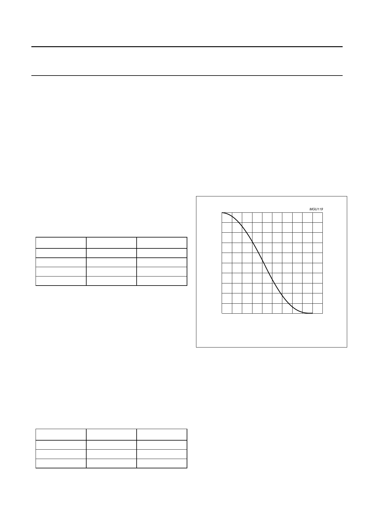
8.6 Mute
Muting the DAC will result in a cosine roll-off soft mute,
using 32 × 32 = 1024 samples in the normal mode: this
results in 24 ms at fs = 44.1 kHz. The cosine roll-off curve
is illustrated in Fig.4.
This cosine roll-off functions are implemented in the DAC
data path before the digital mixer and before the master
mute (see Fig.5).
In the L3-bus and I2C-bus mode, the setting of the master
mute can be overruled always by pin QMUTE. This quick
mute uses the same cosine roll-off, but now for only
32 samples: this is 750 µs at fs = 44.1 kHz.
handbook, h1alfpage
mute
factor
0.8
MGU119
0.6
0.4
0.2
0
0
5
10
15
20
25
t (ms)
Fig.4 Mute as a function of raised cosine roll-off.
8.7 Digital mixer (DAC)
The ADC output signal and the digital interface input signal
can be mixed without an external DSP (see Fig.5).
This mixer can be controlled via the microcontroller
interface.
In order to prevent clipping when mixing two 0 dB signals,
the signals are attenuated digitally by −6 dB before mixing.
After mixing the signal is gained by 6 dB after the master
volume. This way clipping at the digital mixer is prevented.
After the 6 dB gain, the signals can clip again, but this
clipping can be removed by decreasing the master
volume.
2000 Mar 29
9
Share Link: 